In Part 4, we installed the cam tower. I have so far skipped over items like the oil pan, oil pump, water pump, etc. In the great scheme of things, these could be installed by now. Here are a few pointers.
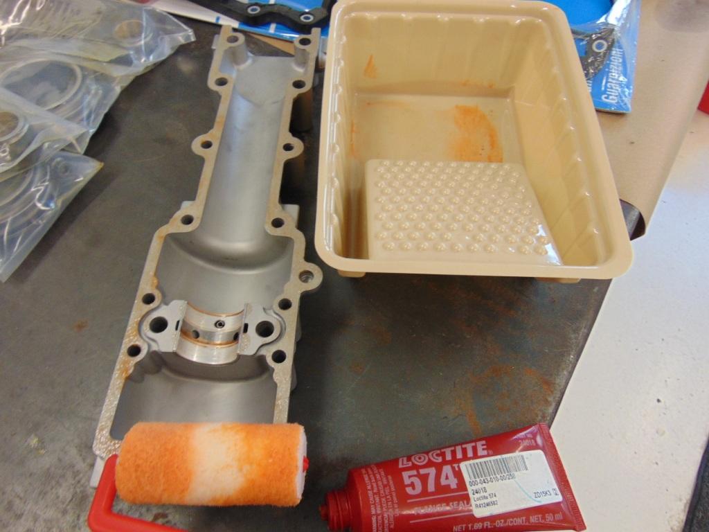
First, we will look at installing the oil pump. When you installed the crankshaft girdle, there was a small check/adjustment important to installing the oil pump. After you put the crankshaft girdle into position but before you tighten its fasteners, you want to take your finger and feel the mating surface at the front of the girdle where it seats next to the block. The girdle can shift fore and aft a small amount. You want to shift it as required so that your finger does not feel any discontinuity or step at the mating surface. This is so when you come back later to install the oil pump, which laps over this surface, there is a smooth surface for the oil pump and its anerobic sealer to seal against. Specs for Locktite 574 say that it can seal gaps up to 0.25 mm. You can use that for guidance if you fit the oil pump and sense there is a gap. Feeler gauges should tell the story as to whether you have a problem or not.
There is not much R&R that can be done to a Porsche 944 oil pump. I understand they have a good reliability record. If you want to see what one looks like on the inside, check out my article about the function of the oil pump here. You will of course want to clean it up externally and flush its internals out with solvent. The drive gear should easily rotate with your fingers. There are subtle differences in the lengths of the fasteners for the oil pump. Before you begin final assembly, drop a fastener through each hole in the pump and make sure they extend a sufficient amount on the backside. Suggested minimum thread engagement is generally considered to be 1 ½ times the fastener nominal diameter. Note that the PET provides info on the OEM fastener lengths but the picture as to which go where is hard to understand.


The thickness of the oil pump where the bolts pass through it varies. Make sure you get the right bolts in the right holes to obtain a bolt engagement of roughly 1 1/2 x the bolt diameter.
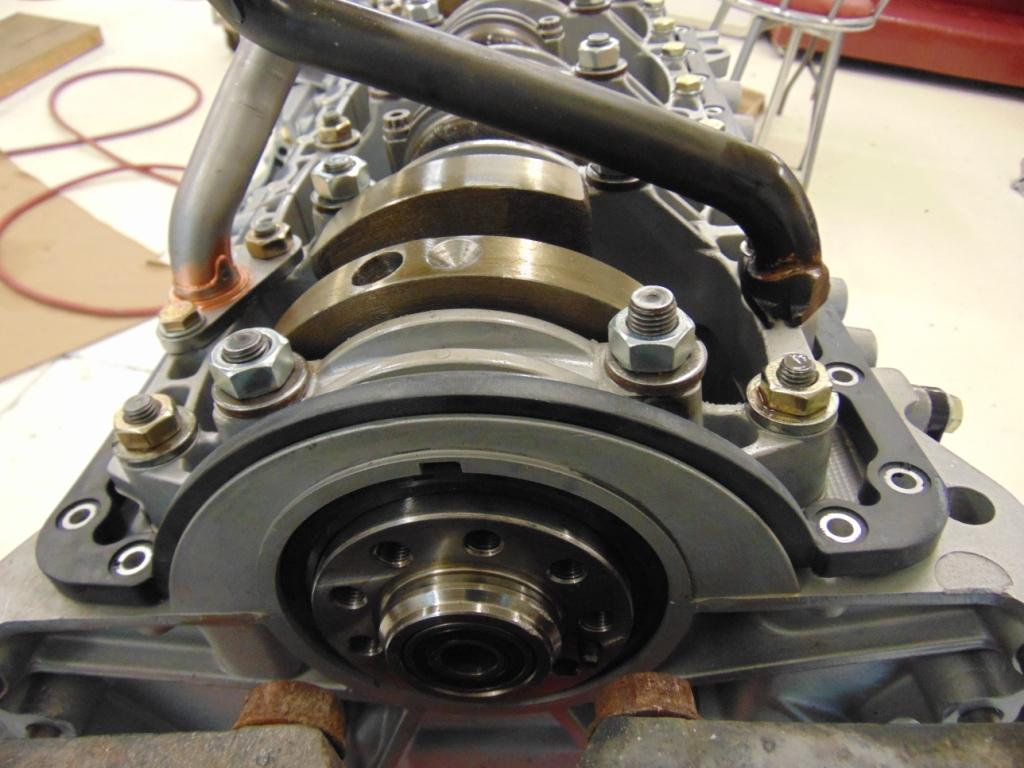
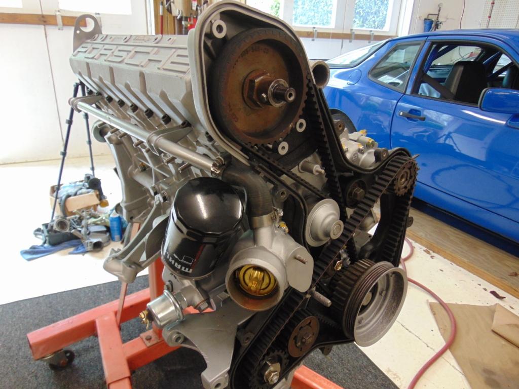
Before you install your oil pump, I would suggest giving the splined drive sleeve that slides on the crankshaft a test fit. If it doesn’t go on smoothly, clean up the crankshaft with sandpaper until it does. Trust me, once this puppy is fully engaged into the oil pump, it is very hard to get back out if it is stuck in any way. If you get the shaft cleaned up enough to accept the drive sleeve, the other pieces such as the cambelt drive gear will also fit on much easier. Use the Porsche PET to help you understand the order of the various pieces on the crankshaft. For some reason you have to refer to both the crankshaft page and the timing belt page in order to get the complete picture. I will note that there is a small rubber o-ring, typically green, that goes on right after the splined drive shaft. This is an important item to keep oil from leaking out of the front of the crankshaft. This is also a good time to address any fitment issues with the woodruff key. Note that the splined oil pump drive sleeve does is not keyed. It is locked in place purely by the large torque that is applied to the bolt on the end of the crankshaft.

Order of assembly for the various pieces that go on the crankshaft snout. Note this shot was taken without the oil pump in position. The first item shown in the splined drive sleeve that will engage the internal gear of the oil pump.
Once you’ve got everything lined up, refer to the shop manual for the discussion regarding where the Loctite 574 sealer goes on the oil pump. Assemble the oil pump to the front of the block and torque the fasteners to the values given in the shop manual.
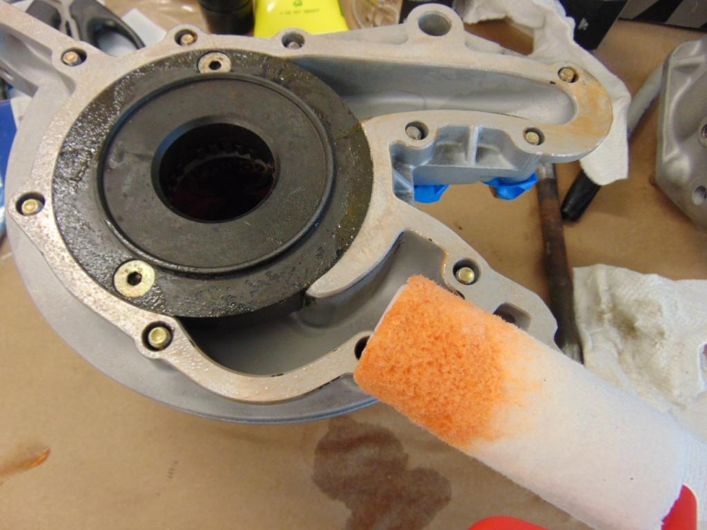
Applying Loctite to the mating surface of the oil pump.
Now we can turn our attention to the oil pickup tube and the oil pan. There is anecdotal information that the pickup tube can crack, allowing air instead of oil to be sucked in, with major engine failure following. Take it from me, don’t fart around with bandaid fixes such as little welded on brackets, just buy a new pickup tube from Porsche. It represents a few hundred dollars well spent and you’ll be fixed for the next 35 years. Note that the tube is brazed into a lug, just like on a bicycle frame. The brazing technique minimizes heat input, minimizing the heat affected zone next to the weld. Any other type of welded bracket added on that uses other welding methods will add excess heat and weaken the joint. The corresponding oil return tube operates only as an ambient pressure drain. Your original one can be used again without fear.

There are two things that I find tricky about installing the oil pickup tube. The first is which gasket to use where it connects to the crank girdle. None of the ones supplied in the bulk gasket kit seemed correct. My best advice to is buy an OEM gasket from Porsche, about $2, rather than trying to guess which gasket in your bulk gasket kit was meant to be the one. This is an area where a few dollars spent can save thousands.
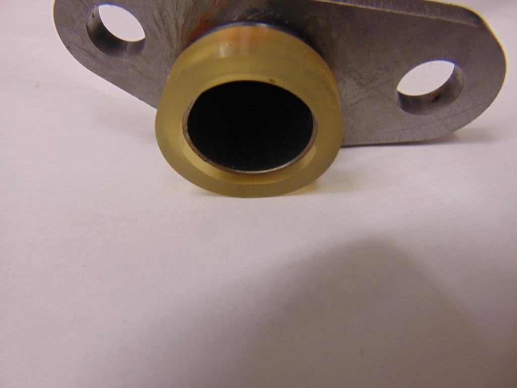
OEM seal as supplied by Porsche for the oil pickup tube.
The other tricky issue is how to apply the proper torque to the single large nut that holds the pickup tube in place. To do it right, you will need a “crowsfoot”. See the picture below. By the way, the use of a crowsfoot does not affect the torque requirement of the nut in any way. Use the same value as you used for all the other similar nuts on the girdle, as specified by the shop manual. For the small screw that attaches the pickup tube and the return tube together, use Locktite to ensure this minor connection does not come apart.

Crowsfoot required to get a torque wrench on the nut for the oil pickup tube.
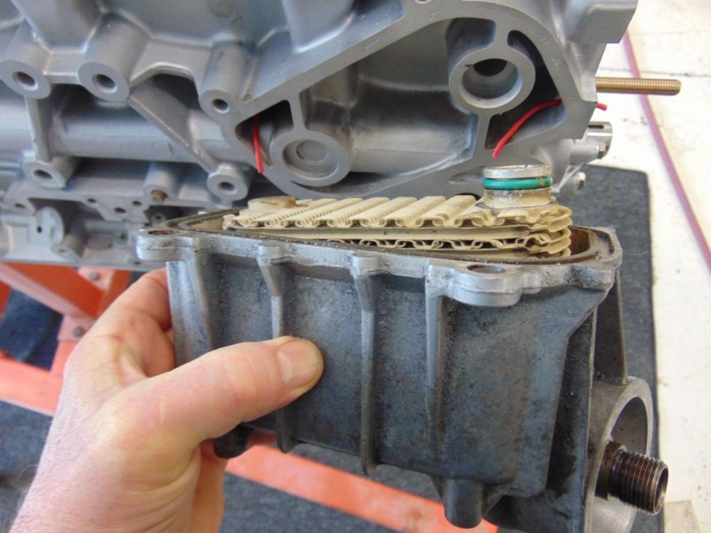
Beyond those items and a thorough final cleaning of the crankcase area with brakeclean, it is time to install the oil pan. But first, I would like to mention a couple of things about the oil pan. The article I have written here, about the Porsche 944 oiling system, describes some attributes of the system. One thing that I like is to use the oil pan from a later car that has the built in scraper for the crank. As discussed in the same article, I am not very convinced that the trap door mechanisms sold as an aftermarket fix to rod bearing failures are necessary. But I’m not going to hash that out here. Use your own judgement. Finally, if you have the plastic oil pan baffle with plastic tabs (versus screws) that hold together the hollow void that is part of the baffle, I would recommend getting a new baffle,. I have found too many of these baffles with broken tabs to trust them at this point. Also, inspect the oil drain plug. If the threads are goobered up, now is an easy time to repair them with a helicoil.

An example of an oil pan baffle where most of the tabs to hold the hollow void in place have failed.

New oil pan baffle. It uses screws instead of tabs.

Oil pan baffle in place. I would apply blue Loctite to those little screws that hold it in place.
It can be a real hassle to install the oil pan and its gasket with the engine in place in the car. Conversely, with the engine on a stand and inverted, it’s really not a bad job. Use a new gasket, which should come with your gasket kit. Use your thread chasers to make sure the holes for the fasteners are clean and easy to thread into. Lay the gasket into position and carefully install the oil pan over the oil pickup tube. Working from the middle and going outward, get the screws started through the pan, the gasket, and into the block. The gasket always needs to be stretched a little at each corner but as you work your way out it will gradually move into position. A small phillips head screwdriver is useful to insert in the holes and pull the gasket into position. Note that the screws at the outside 4 corners are longer than all the others. The workshop manual gives 3 levels of torque. I find you will go around the perimeter a lot more than 3 times until you can get all the screws installed to a consistent level of tightness. If you removed it, the guide tube for the dipstick should be re-inserted, making sure it is fully seated into its hole.

Oil pan gasket viewed from the front of the engine.
Oil pan gasket viewed from the rear of the engine.

Oil pan in place.
Next, let’s move on to the waterpump. If you haven’t changed out your waterpump in a while, it is probably a good idea to do so. One thing that I did on my engine was to put in helicoils and studs at all the waterpump fastener locations. This is not so much a strength issue as one of corrosion. I have had multiple cases where the waterpump screws would not fully torque without stripping their threads. I suspect coolant works its way down into the threads in the block and sets up galvanic corrosion, eating away the threads in the aluminum block material. Once you use helicoils and studs this will never happen again, or at least you won’t care since you will never have to dis-assemble these fasteners again! The waterpump comes with a paper gasket. It does not require any sealant. Torque the fasteners as specified in the workshop manual. For the same reason, I like to replace the screws with studs at the housing that is mounted on the top of the cylinder head, where the coolant outlet hose is attached. I cut the studs from bulk threaded rod material that I bought from McMaster-Carr.

Waterpump bolts replaced with studs.

Waterpump in place. I assumed ny-lock nuts to prevent loosening and aid in dis-assembly.
While you are in there, get a new thermostat installed in the large inlet opening to the waterpump. Be sure and get the correct thermostat from a trusted supplier such as Paragon or Pelican. It is a known problem that some aftermarket thermostats do not seal off the bypass opening correctly. For more info on the cooling system, see my article here.

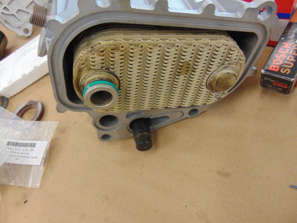
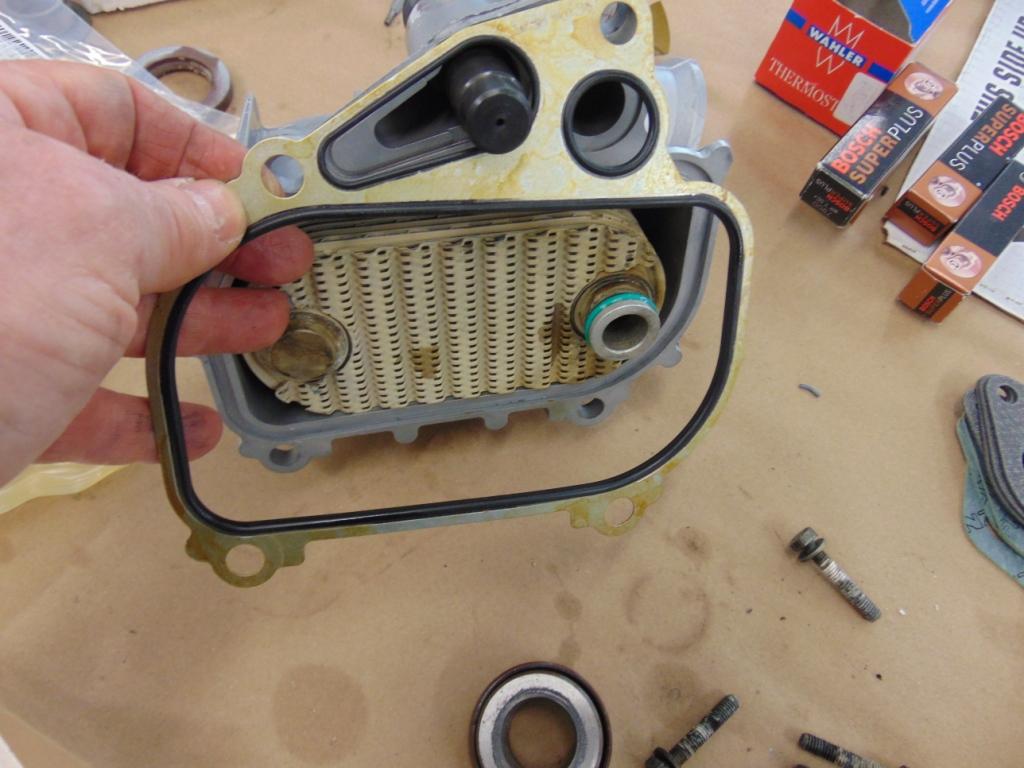
Next, you can install the oil cooler housing. Depending on your car, you will have the standard oil to water cooler or the one with an external oil cooler. You will also come across a range of oil pressure relief valve designs, which Porsche changed over the years. Make sure you clean the cooler housing as well as you can. It typically has an internal buildup of stuff that has precipitated out of the coolant. Money well spent is to replace the internal heat exchanger unit, both to ensure that heat transfer is back up to original standards and also to ensure that there are no metal shavings caught in the small passageways from previous bearing failures. Your gasket kit will come with new o-rings and the special gasket that fits between the housing and the block. No special sealants are required. The housing is held on with 4 bolts. Much has been written about getting the housing aligned perfectly so as to not have the oil pressure relief valve bind. I sucked it up and purchased the Porsche alignment tool to make sure everything was in line. I would recommend purchasing a new oil pressure sending unit to install.
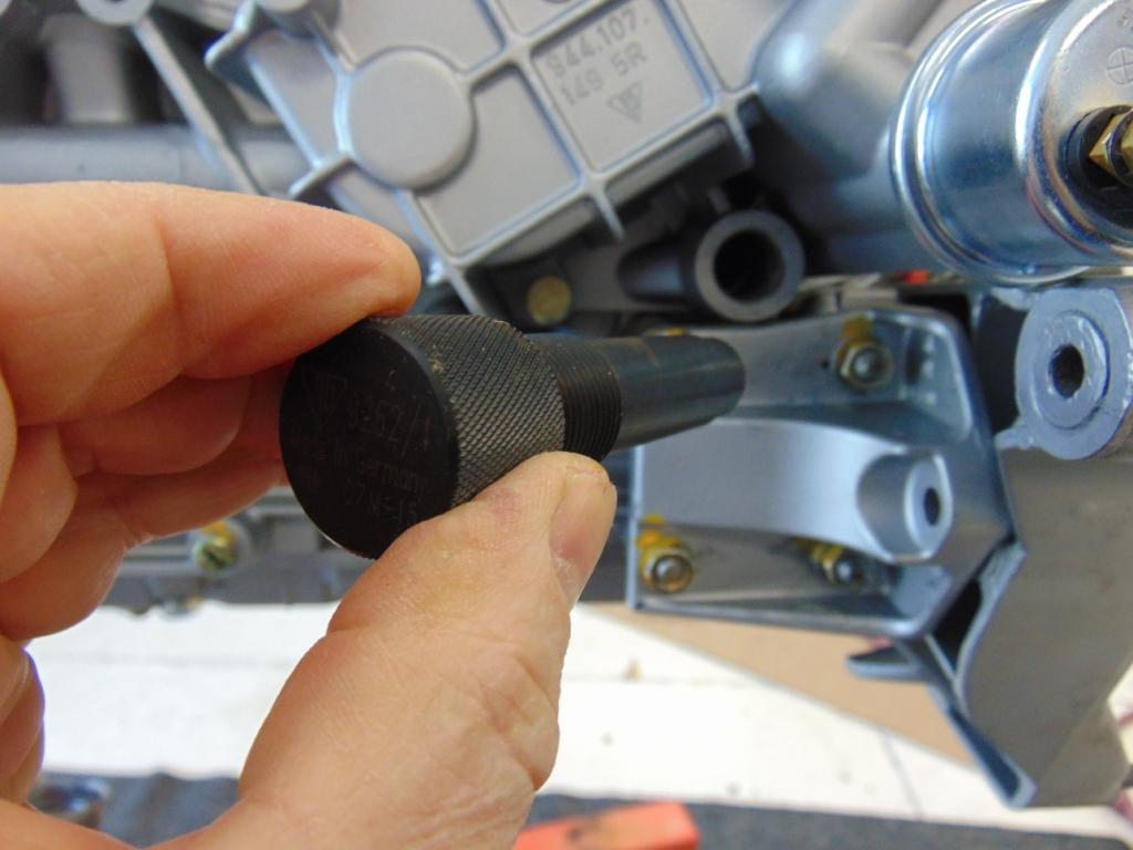
Oil pressure relief valve alignment tool.
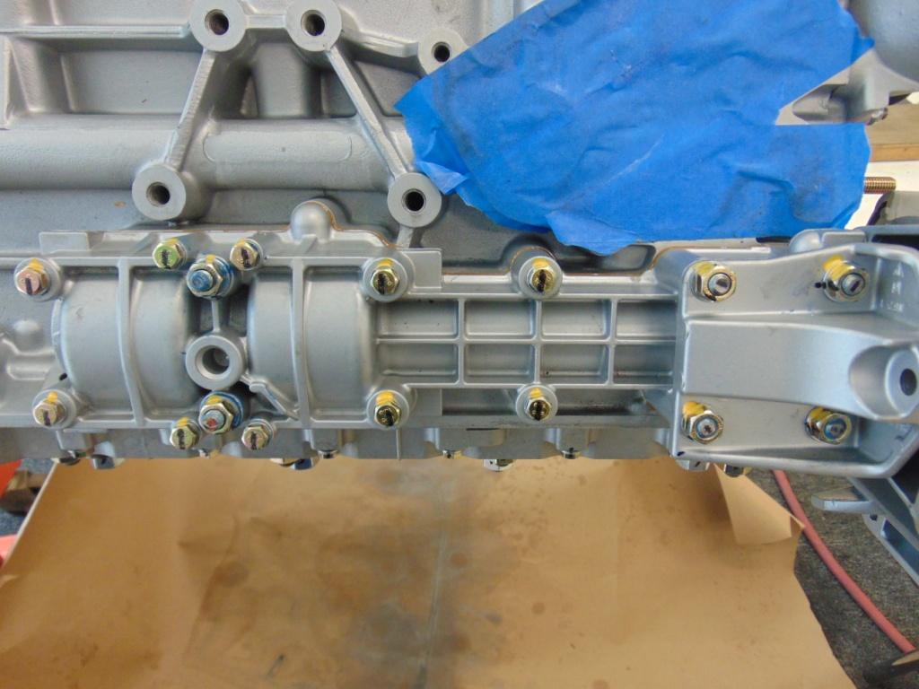
Last but not least, it is time to install the balance shafts. I don’t know if it was just me but I had a hard time getting the balance shafts installed such that they would rotate freely by hand. Wanting to do a thorough job, I replaced the balance shaft bearings. There are 1/2 shell bearings on the interior end of the bearing and fully circular bearings at the outer end. The fully circular bearings must be pressed in. The 1/2 shell bearings install just like the rod bearings. I did not check the bearing clearances with Plastigage and there is a chance that I ran into some mis-manufactured bearings. At my first installation, one balance shaft would not turn at all by hand. I purchased an additional set of bearings and after using them, it turned but still seemed very stiff. I think the final part of the puzzle is to torque the various fasteners rigorously in accordance with the pattern and values shown in the workshop manual.

The 2 block objects are just plastic pieces opposite of the actual eccentric balance weights. These plastic pieces do not come on the earlier engines. The 1/2 shell bearings are located between the 2 balance weights. The fully circular bearing is a press fit inside of the fitting at the right hand end of the shaft in this picture.

I added studs to replace the larger bolts for my balance shaft.
Note that the balance shaft cover gets Loctite 574 sealant.
Balance shaft cover in place. Note that this is a cover for a turbo engine and it thus has an oil feed opening, which I will have to plug.
On my build, I found something weird in that the round o-ringed plug at the back end of the balance shaft housing was loose even after everything was assembled and torqued. I suspect the o-ring in the gasket kit was not the exactly correct one for the job. As there is virtually zero oil pressure applied to this joint, I supplemented it with RTV silicone to ensure a good seal. In retrospect, I should have ordered OEM o-rings. At the lower balance shaft, at the front housing, make sure you assemble the little right angle reinforcing bracket, as it is hard to install after the fact.
As far as installing and aligning the sprockets on the front of the balance shaft, I can only recommend that you refer to Clarks-Garage, where there is an excellent set of instructions on how to get the various critical steps right. Clarks-Garage will also lead you through the steps of installing the timing belt and balance shaft belts. I use a kit that I purchased from ArnnWorx. I like the Maxikit, which has tools to adjust belt tension, hold the balance shaft gears for tightening, and locking the flywheel. This kit has earned its keep many times over.
I think I am going to stop this series of articles here. The remainder of the process is not re-building the engine as much as re-installing things in the proper order. There is of course a long list of items left before you are done. Once you take the engine off the engine stand, you can install the flywheel, clutch, and bellhousing. Porsche 944 clutch kits are surprisingly expensive. That said, there is no better time to replace the clutch with new items. Use your thread chasers to clean the 4 holes on the back of the bellhousing so that when you are in that difficult step where you are trying to get the torque tube re-attached, you are at least not fighting reluctant fasteners. While you have the engine out, this might be a good time to review the condition of your brake master cylinder, the brake booster, the clutch master, and the clutch slave. There will never be an easier time to replace them. I also purchased a new steering shaft, the one with the swivel joints, and installed it before I put the engine back in. Much, much easier. And for God’s sake, be sure and thread that same shaft through the correct spot between the block and the motor mount. Get it wrong and you’ll be cursing. Ask me how I know! I like to install the engine from below. I check the angle of the torque tube with my digital protractor and then carefully adjust the rigging of my hoist to hold the engine at the exact same angle. Doing this, insertion of the driven shaft into the clutch and flywheel bearing went smoothly. Also, buy and use a clutch pressure plate alignment tool when assembling your clutch.

One final tip. I like to paint all my external fasteners with a dab of nail polish right after I torque them. The factory used yellow! Use a Sharpie on internal fasteners exposed to oil. This serves 2 purposes. It is a good reminder that torque was applied. And in the future, if an external fastener starts to back out, you will have a visual reference that something is wrong, since the nail polish will be disturbed. For the internal fasteners, you just to have trust that a correctly applied torque with keep the joined parts together for the life of the engine. That is what torques are designed to do!
Take your time. Be methodical. Be fanatically clean. Follow the shop manual. Refer to the PET. Buy your parts from our trusted suppliers like Paragon and Pelican. You will be rewarded with a sound strong reliable engine rebuild!
Special tools:
17 mm crowsfoot
Torque wrench
Arnnworx Maxi Kit

Discussion
Comments are closed.