Due to much discussion regarding why the Porsche 944 engine can tend to trash the #2 rod bearing, I took the opportunity to look closely at an engine to see how the oiling system worked. As you look at the oiling system layout, you can begin to understand how the #2 bearing might be at risk. And to jump to the conclusion, #2 appears to be at risk for seeing an oil supply with a high percentage of oil with air bubbles in it. Stay tuned and all will be revealed.
Note: A picture is worth many words so I’m going to try and minimize words and maximize pictures. Note that most of the pictures are of an engine turned upside down so don’t let that confuse you. The engine shown is from a 1984 car.
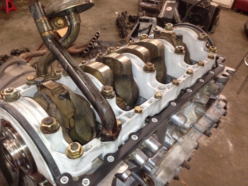
Most of us understand that the oil starts its journey in the sump. Pooled in the bottom of the sump, it enters the oil pickup tube.
Oil pickup tube with screen. Oil return tube (no screen)
Oil pickup tube with screen. Oil return tube (no screen)
In the above picture, the oil return tube is in the foreground and the oil pickup tube is in the background. Both tubes attach to the “crank girdle”. In the next picture we’ll see the passageway that lies under the crank girdle, on the bottom side of the block, that transfers the oil from the pickup tube to the oil pump mounted on the front of the engine. I have used red wire to highlight the passageway. This picture is looking at the front of the block, without the oil pump mounted in position.
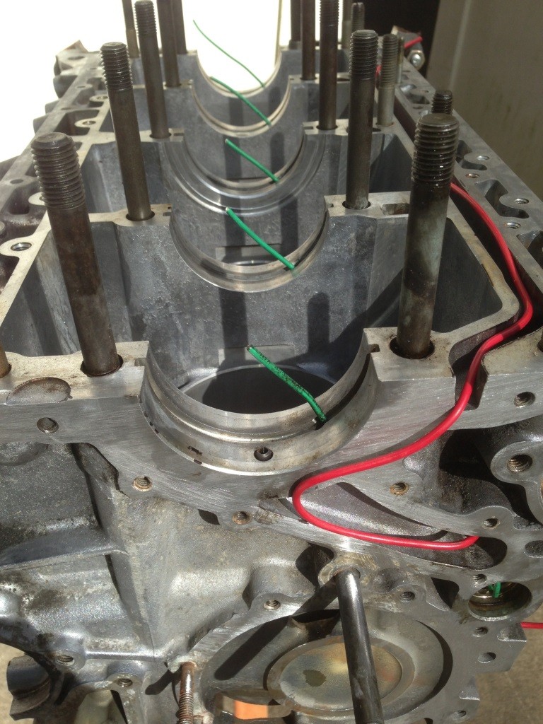
There are a couple of things to note about the above picture. The oil pump is not mounted but if it were, it would suck the oil from the passageway and insert it under pressure into the hole in the front of the block where the red wire disappears into. The green wires are stuck into the oil passageways for the crankshaft main bearings. We’ll come back to them.
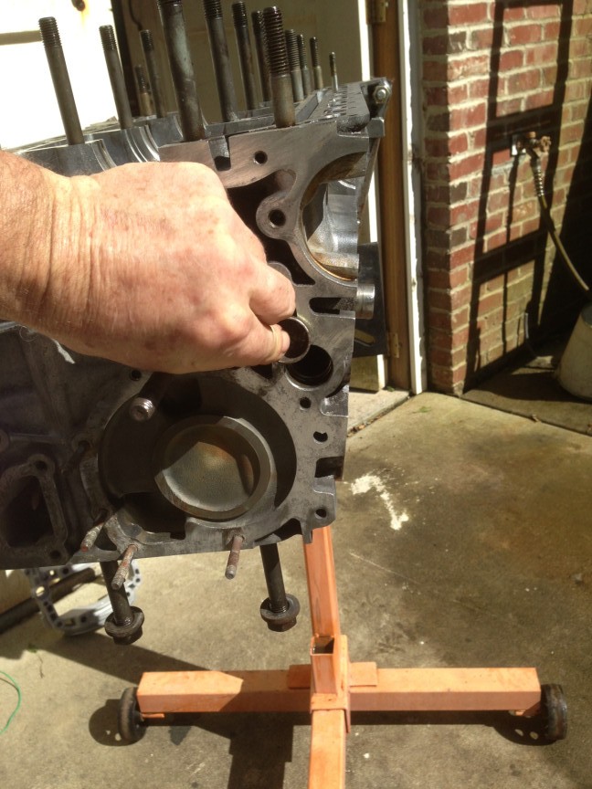
In the above picture the red wire enters the front of the block. Near its entry point is a round hole. This hole is normally plugged with a cap. This hole passes through the length of the block and is the main “oil gallery”. The following pictures show the cap. There are caps at both ends of the block so if you remove them both, you can give the gallery a really good cleaning. I highly recommend this. The caps are destroyed upon their removal but new ones are like $2 a piece.
Oil gallery cap
Oil gallery cap
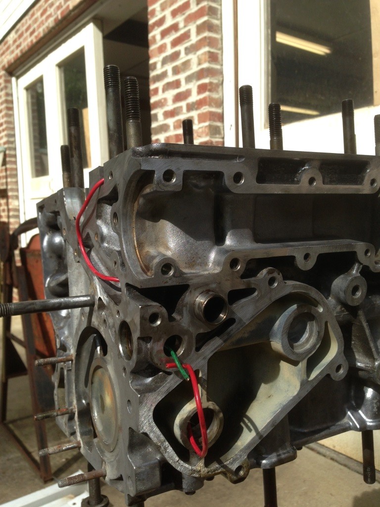
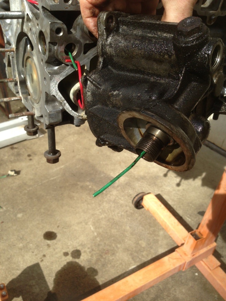
Now we’ll look around the side of the block where the housing for the oil cooler (on a N/A engine) and the oil filter attach. Its hard to show but I have used a red wire to show the hot uncooled oil and a green wire to show the cooled filtered oil. It is important to note that the flow back into the block is pointing right at the #1 crankshaft bearing, with no turns or changes in direction required. Conversely and very important, the oil for the rest of the engine has to go around the first of several 90 degree corners to get into the oil gallery. The second picture shows the fitting for the oil filter.
So let’s go back to that photo of the block without the crank shaft or bearings installed. There are 5 crankshaft bearings on a 944, a very robust design. Note that each bearing has a passageway drilled from the bearing back to the oil gallery. These are shown by the green wires in the photo. If you could see the other end of the green wires, you would see them sticking into the oil gallery, at a right angle.
Green wires show the drilled passages for the crankshaft bearing oil supply.
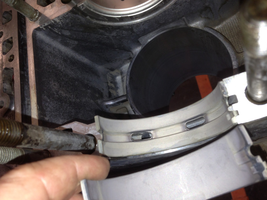
Here is another picture with the bearing shell ready to be installed. You can see how the oil is allowed to get through the bearing and flood the narrow space between the bearing and the “journal” on the crankshaft. A “journal” is the smooth shiny very hard surface on the crankshaft that serves as 1/2 of the bearing surface. The other half of the bearing surface is formed by the bearing shell, which is hopefully the wear item that can be replaced during an engine rebuild.

 So the oil floods the space between the bearing and the crankshaft journal. Where does it go from there? The answer is revealed by a close examination of the crankshaft. This is a little hard to show because all the passages are internal to the crank. First, each crankshaft journal is drilled with a hole radially towards its mid-point. This hole is intercepted by a diagonal hole that heads off towards the rod bearing journal. There is a hole drilled radially through the rod bearing journal that intercepts the diagonal hole. Note that the diagonal hole is plugged at its end, once drilled, to blank it off and force the oil into the rod bearing journal area. So the oil goes radially inward from the crankshaft journal, then diagonally outward towards the rod bearing journal, then radially outward to the surface of the rod bearing journal. Whew! Here are a few pictures.
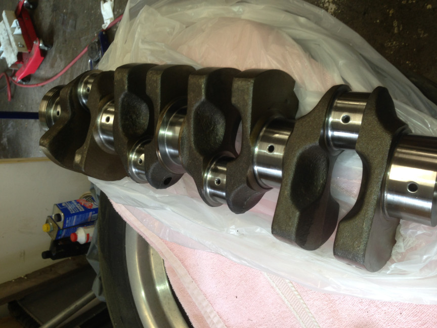 Note that the crankshaft journal surfaces are much bigger than those for the rod bearings. From this you might deduce that the rod bearings are more highly loaded due to their smaller surface area.
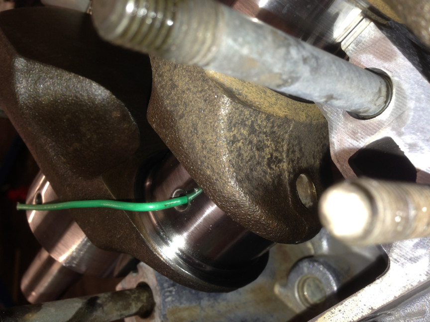
 In the above 2 pictures, I have just run the green wire externally to the internal passages in the crank, to give you an idea of how they run. The actual passages are hidden. If you look closely to the right side of the above picture, there is a machined hole. This is where they inserted the drill to make the passage, then installed a plug. Also note that if the rod bearing journal is “cross drilled” the hole shown in the above picture extends all the way through the rod bearing journal. If it is not cross drilled, it only extends halfway through the rod bearing journal. Regardless of either design, 100% of the oil coming out of the diagonal passageway reaches the bearing. But being a zero sum game, I don’t see that cross drilling does anything to improve the oil supply, as there are so many passages before it that serve to limit the flow. Think of it like the interstate leading into Charlotte. Its 2 lanes north of town and then opens up to 4 lanes nearer to town. But during the morning rush hour, the 2 lane section is stop and go. Having the 4 lane section down the road really doesn’t help much because the 2 lane section is the restriction to flow. Indeed, I have seen that early cranks (83, 84) were cross drilled by Porsche but later cranks are not.
FYI, near the rear end of the oil gallery there is yet another 90 degree branch that shoots straight up, goes through the headgasket, and enters the cam housing to lubricate the cam. EDIT: A more detailed discussion regarding this flow path has been added at the end of the article.
So finally the oil has reached the rod bearing. If all goes according to plan, the space between the rod bearing shell and its journal stays filled with a very thin layer of oil at all times and all is well.
Now a diagram would be in nice. But in words, we see that the oil to the 1st rod bearing has no 90 degree turns and two 45 degree turns. The oil to the #2 rod bearing has a 90 degree turn to get out of the oil gallery and then two 45 degree turns. The same is true for the #3 and #4 bearings. It is worth noting that the oil for all but the first crankshaft bearing also goes through a 90 degree turn.
So my theory (not original to me but I subscribe to it) is that the oil in the sump is “aerated” (air bubbles are introduced into the oil) by the crank beating the oil like an egg beater. This mixture of oil and trapped air bubbles runs through the path described. Every time it goes through a change in direction the air, being lighter, is happier to go around the corner than the oil is. That is not of consequence until there is a split or branch in the passageway. The air bubbles are willing to go around the corner, the oil not so much. As we have seen above, the oil coming out of the filter/cooler goes straight on to the 1st crank bearing (and eventually to the 1st rod bearing). It has to go around a 90 degree corner to enter the oil gallery so all the oil going to crank and rod bearings 2 through 4 has a higher concentration of air bubbles. When it gets to the first branch off the oil gallery going to the 2nd crank and rod bearing, the air once again is selected preferentially as it is more willing to go around the 90 degree corner. For the 3rd crank and rod bearing the phenomena is the same but the bulk of the air has been extracted. By the time it gets to the passage for the 4th crank and rod bearing, the oil has been de-aerated pretty well. Ditto for the oil going to the last crank bearing and up to the cam.
So I believe that the culprit is the air entrained in the oil and the design of the oil passageways. And what are some remedial solutions? Here is what I have come up with.
- Street use typically means lower rpms and less frothing of the oil. Don’t rev your engine so much!
- Hell, I want to rev my engine! So use a good quality oil that minimizes foaming. There is a long and opinionated discussion about what that oil should be. Check the archives or Bobs the Oil Guy. Personally I use Valvoline Racing oil.
- Use a synthetic oil.
- Use the correct viscosity. More discussion and opinions abound. I use 20W-50.
- Keep your oil filled to the mark but do not overfill. Overfilling just increases foaming.
- For heavy track use, use aggressive oil change intervals.
- Get a crank scraper to help minimize the foaming. Alternatively use an oil pan from a later model 944 that has a built in crank scraper. See article here.
Except for the crank scraper, all of the above can be done by any and all of us that want to track our cars without too much effort.
As I discussed above, I think cross drilling the crank has no value. I do think that oil pickup extenders and sump baffles are a good idea but more for preventing general oil starvation in long sweepers than anything else.
So there you go. The oiling system for the 944 is reasonably straight forward. And a good oil supply is the life blood of a high performance engine. Treat it well and it will hopefully treat you well.
OIL FLOW AT THE HEAD – SINGLE OVERHEAD CAM ENGINE
Edit- Feb 2018
After performing a recent full engine rebuild, I did an inspection and established the flow path for the oil in the head, specifically at the Cam Housing. There is technically no pressurized oil lubrication required in the cylinder head. Oil lubrication is required at the camshaft housing, which is the casting with PORSCHE imprinted on it that you see when you look down on the engine. This casting holds a single overhead cam, which is driven by the camshaft belt. The belt you need to change on a routine basis, before it breaks and trashes your engine! But that is another article.
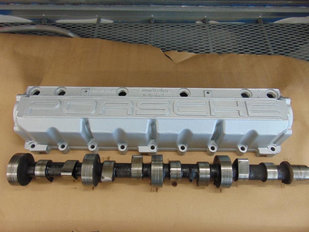
Camshaft Housing with camshaft removed
Anyway, it turns out the camshaft needs lubrication for 2 reasons. The camshaft rotates in 5 bearings that require lubrication. There are also hydraulic valve tappets, commonly known as “hydraulic lifters” or “cam follower buckets” which require oil pressure for both lubrication and to establish sufficient hydraulic pressure to keep the tappet firmly in contact with the camshaft during all operating modes.
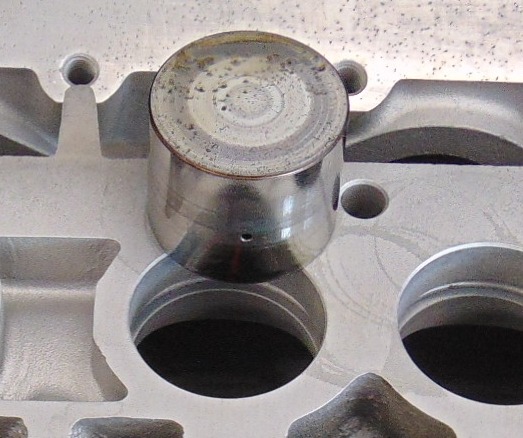
Hydraulic tappet
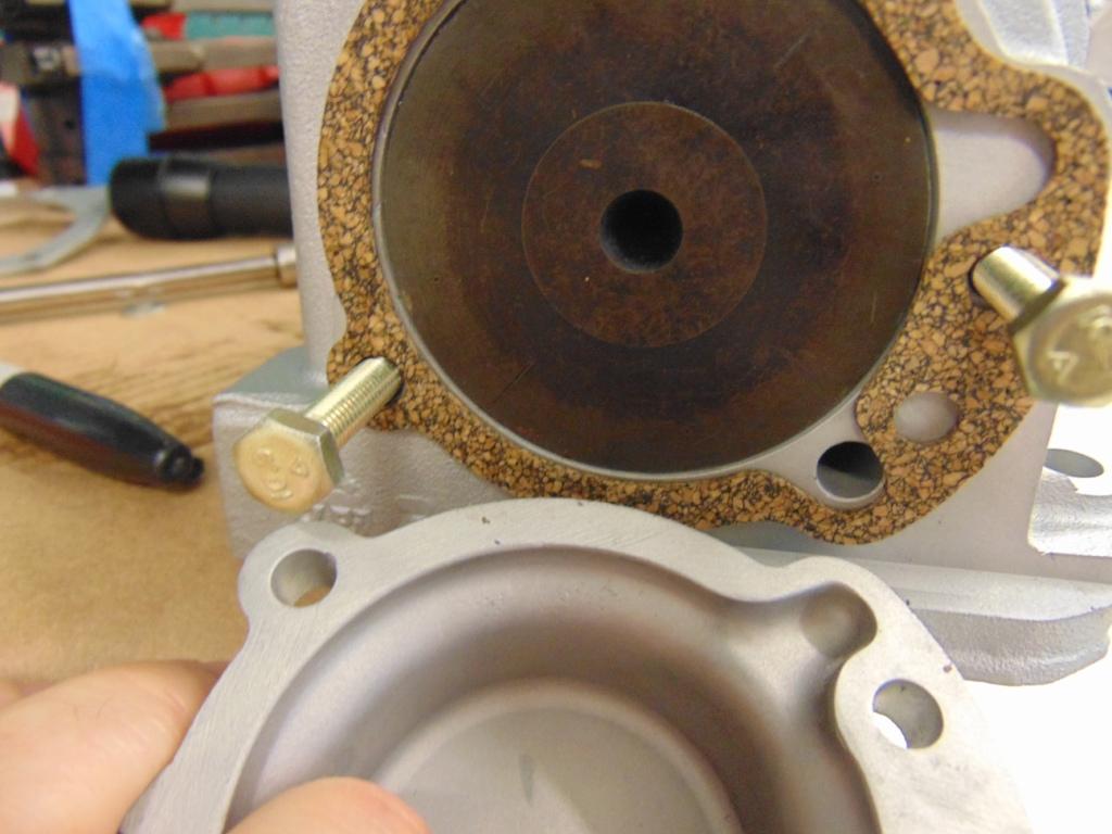
Previously in this article, we discussed that there is a large horizontal passageway in the block which has branches that feed the various crankshaft bearings. Towards the rear of this horizontal passageway there is an intersecting vertical passageway that leads straight upward, through the block, through the cylinder head, and into the camshaft housing. This passageway is not particularly exciting to look at but it does have one interesting feature. Embedded in the cylinder head, there is a small round ball. This ball is spring loaded and serves to only allow oil flow upward when the engine is operating. When the engine is shut off, this “check valve” closes and prevents all the oil in the camshaft housing from draining by gravity back into the oil sump. In this way, oil supply to the camshaft is supplied immediately upon engine startup.

Oil check valve embedded in the cylinder head.
The above picture gives a top view of the cylinder head, showing the passageway with the check valve ball. When the camshaft housing is fitted to the top of the cylinder head, this passageway aligns with a oil distribution network in the camshaft housing. This distribution network is what we will discuss next.
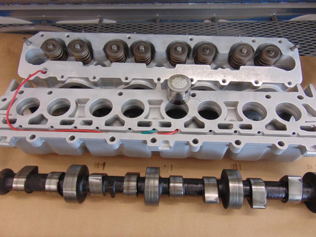
Top of cylinder head. Bottom of camshaft housing.
In the above picture, the camshaft housing has been flopped over from its normal position on the cylinder head. The 8 large holes hold the hydraulic tappets, one of which is shown in the picture. When the lobe of the camshaft presses on the tappet, it transfers this motion to the end of the valve stem, thus opening the valve. The smaller rectangular shaped holes are oil return passageways. They allow return oil to drain out of the camshaft housing back into the cylinder head. From there, return passageways in the cylinder head (not visible in this photo) allow oil to drain through the head and through the block, all the way back to the sump. This area in the head, around the valve springs, is not fed by any oil directly under pressure, rather it is a “splash” system where the motion of the moving parts tends to pick up the oil that is coming back from the camshaft housing and splash it on the moving parts, which in this case is the valve springs and the portion of the valve stem sticking above the valve guides embedded in the cylinder head.
Getting back to the camshaft housing, the long red wire on the left hand side of the above picture is an extremely exaggerated representation of the oil supply path from the cylinder head into the camshaft housing. When assembled, the oil passageway in the cylinder head lines up with the long horizontal passageway in the camshaft housing. This passageway fills with pressurized oil . The oil leaves the passageway in 2 important ways. The short green wire shows one of five side passages that feed the various bearings visible on the camshaft. Note that Porsche designed the camshaft bearings without replaceable bearing shells. The round cylinders visible in the photos engage matching round holes machined into the inside of the camshaft housing. The oil passageways emerge on the perimeter of the machined hole and provides pressurized lubricating oil to the bearing surface. The oil that exits the sides of the bearing is returned by gravity to the sump, as discussed above. In just a minute, we’ll look at how the two end bearings have special return passages but first let’s talk about the hydraulic tappets. In the above picture, the short red wire leads to a side passageway which leads directly to one of the 8 large bores that contain the tappets.
Hydraulic tappet
The tappets are difficult to look at and see how they function but in general, there is a top and a bottom to the tappets that is separated by an oil filled space. The volume of oil in the space determines the height or thickness of the tappet. If the tappet were machined out of a single solid piece of metal, they would be fixed in their height. My Jag E-Type has this type of system. The exact height of each tappet is dialed in using thin circular shims. Since there is no one correct height for all operating conditions, the tappets can be a little noisy, say upon cold startup, when all the parts have not come up to temperature. Except for very high performance engines, manufacturers long ago developed hydraulically actuated tappets. These tappets can compensate their operating height “on the fly” so to speak in response to changing conditions. The exact mechanics of this remain a mystery to me but suffice it to say the internal construction of the tappet allows it to “pump up” or grow taller when conditions demand and to also collapse a little or grow shorter, as required. This happens automatically as the engine is in operation. If it has been a very long time since you started your engine, you may hear a loud clatter for a short while after you start your engine. This is because during that time since the engine last ran, some of the oil has manged to drain out of the tappet, leading to a more collapsed position that provides slop in the camshaft actuation. The clatter occurs when the tappet takes up the slop and the parts come together. As soon as the proper oil volume inside the tappet is re-established, the tappet takes up its correct height, the slop if removed, and the parts engage silently.
Some excess oil emerges from the tappets, which will lubricate them in their bores and also lubricate the critical high contact stress surface between the tappet and the cam lobe. That contact surface between the cam lobe and the tappet is one of the toughest lubrication challenges in your engine. This gets into the science of Tribology. This situation is especially tough to keep lubricated because of the very narrow surface profile of the camshaft lobe as it engages the tappet. This involves science that is way beyond my comprehension but, hey, it works!

Camshaft bearing. The oil feed follows the green wire’s path.
In the above picture you can see some faint grooves on the perimeter of the bearing on the camshaft and on the perimeter of the bearing surface machined into the housing. Pressurized oil is distributed around the perimeter of the bearing contact surface and provides a thin film of oil to keep everything running smoothly. Oil is constantly oozing out of the both sides of the bearing. The oil that comes out the front side of the front bearing, like all the oil from the bearings, needs to return to the sump. There is a small hole that leads from the front cam cover back into the main body of the housing, allowing the oil to return.
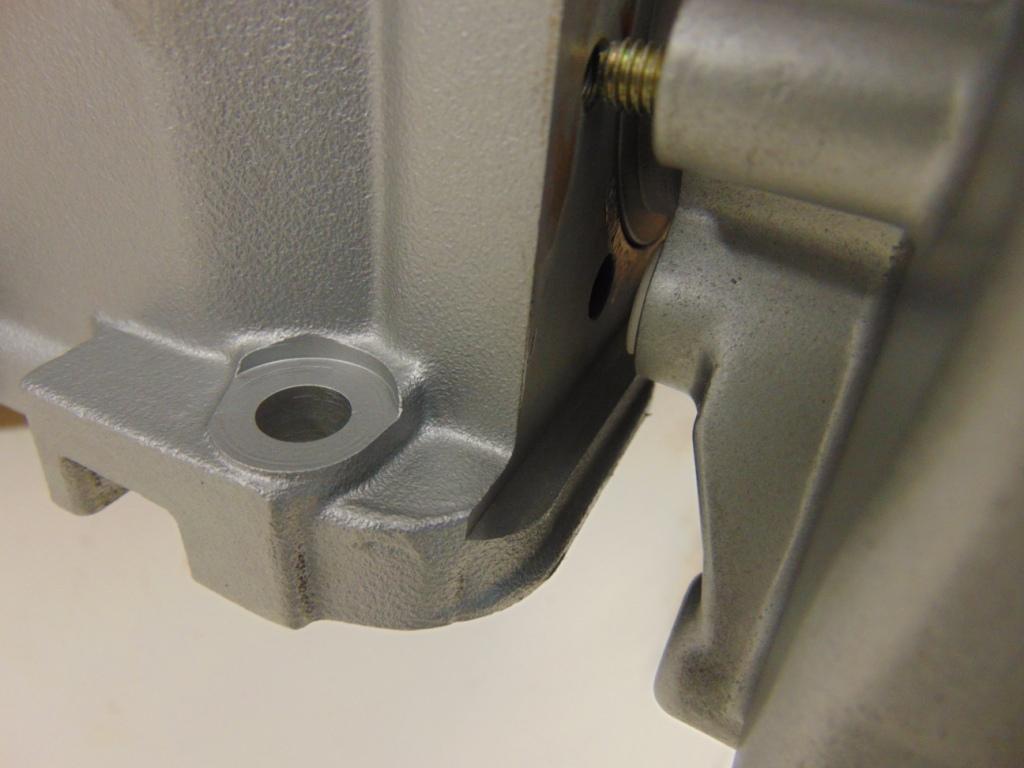
Closeup of the hole from the front housing back into the interior of the camshaft housing, allowing excess oil to return to the sump.
The same situation occurs at the rear bearing. Assembly is fairly foolproof but you must make sure that your gasket has the appropriate cutout to expose the return hole.

Camshaft assembled in the housing. The screwdriver is pointing to the oil return hole. The gasket must expose this hole.
Rear end of the camshaft housing with rear cover removed. Note oil return passageway.
And that is about it. Now you understand better the configuration of the overhead camshaft on an early 944 engine and how the lubricating oil is supplied and returned!
PS I hope you have noticed how nice and clean all the parts are in my pictures. I have spent much effort bead blasting the various parts to get rid of years of grime and baked on oil. Exterior surfaces are painted with Duplicolor Cast Aluminum High Temperature Engine paint.
OIL PRESSURE RELIEF VALVE
After my recent engine rebuild, I was disappointed to discover that the oil pressure gauge was showing about 3 bar at normal operating conditions. Note that 1 bar is equal to approximately 15 psi. I tried another gauge, to no effect. I also bought a new sending unit and installed it, again with no effect. Note you need a ground down (thin) 24 mm wrench to remove the sending unit in place, or I bought a set of inexpensive “crows feet”, which are already thin. I was certainly hoping that the low oil pressure wasn’t due to a mistake in my rebuild. So the last thing I changed, which fixed the problem, was the oil pressure relief valve. Now I’m getting 4-5 bar. Workshop manual spec is 4 bar at 3000 rpm. Following is some discussion about the oil pressure relief valve (OPRV).
First I would direct you to the following article by Dave in London, which had done a nice job explaining some key elements of the OPRV.
http://944foot2thefloor.blogspot.com/2010/07/how-to-remove-and-replace-oprv-oil.html
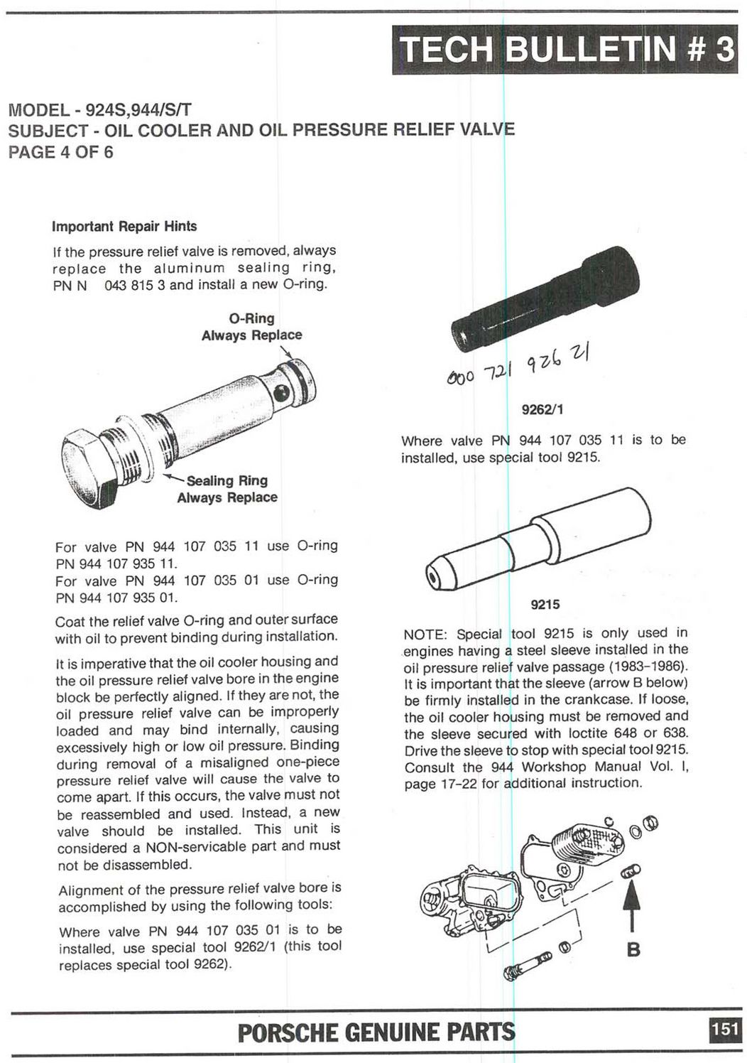
I had always known there was the newer 1 Piece valve and the older 3 Piece valve. What I didn’t know was that there were 2 versions of the 1 Piece valve. My engine is normally aspirated but is based on a used turbo block. It turns out after checking the engine code on the side of the block (just to the rear of the orange/black oil filler tower) that my block was from an 87 car and needed the later version of the 1 Piece OPRV. I had used a valve that I got along with a turbo oil cooler. I don’t really need the oil cooler so I used the oil/water cooler from an 85 N/A car. After reading Dave’s article, in particular the Porsche tech bulletin, I realized that I might have the wrong valve. Not only did I have the wrong valve but when I pulled it from the car, it came out in multiple pieces. And the o-ring on the end of the valve was missing. It’s amazing I had any oil pressure at all! Since I had the valve, in pieces, here is an attempt to show how it works.
My internet reading noted that if the system oil pressure goes too high, the weak link is the oil filter, which will blow out. The highest oil pressure might be expected when the oil is cold and thus very thick or viscous. In essence, when the oil pressure exceeds a certain “setpoint” value, the OPRV will open and relieve the excess pressure.
The OPRV resides just downstream of the oil filter. It’s end is exposed to a vertical oil passage in the side of the block. Here is a picture but it is hard to photograph.
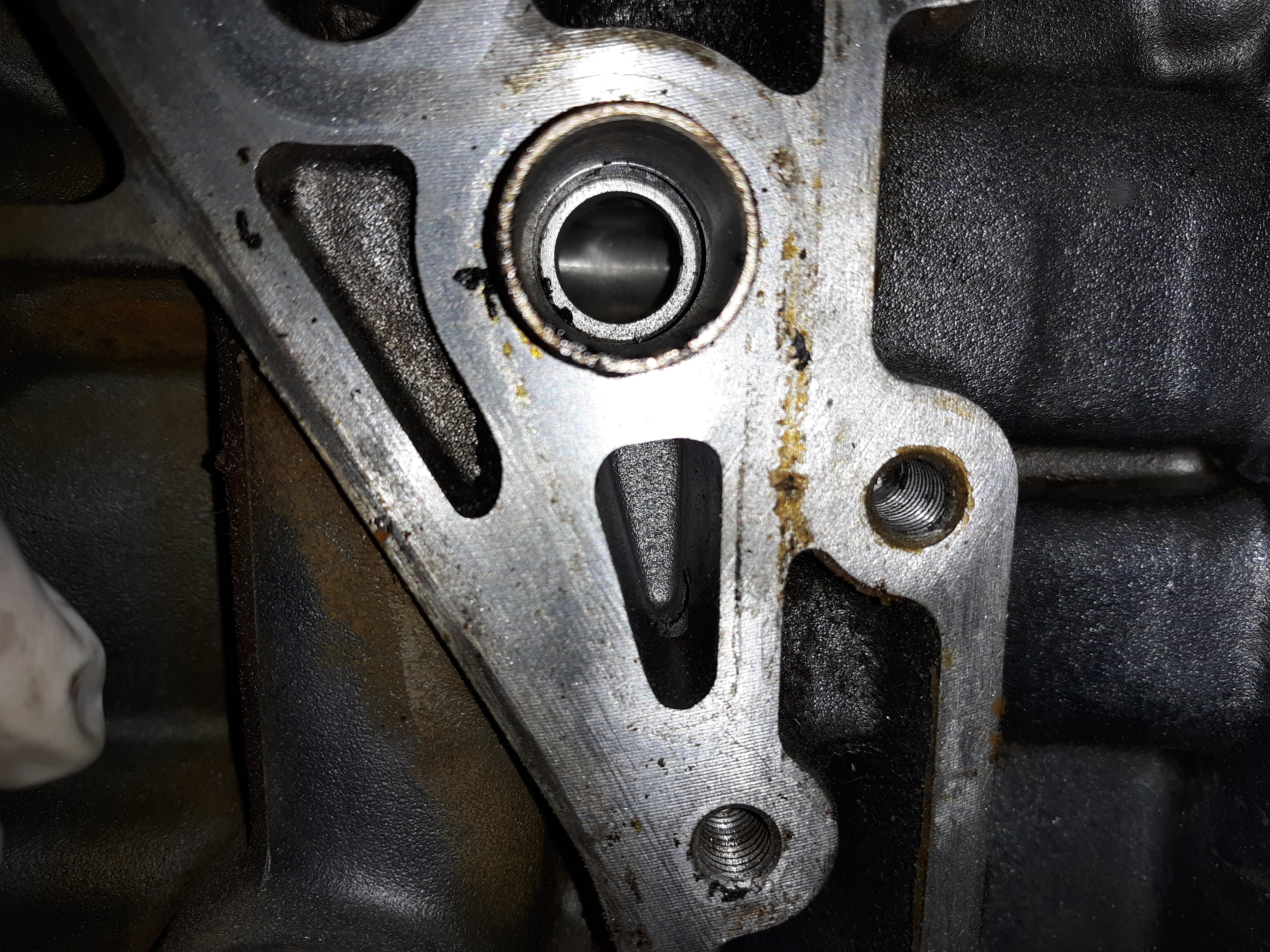
When the OPRV opens beyond a certain point, it exposes a drain path. Interesting to me is that the drain path doesn’t go right to the sump but rather it goes back to the suction channel in the crank girdle for the oil pump.
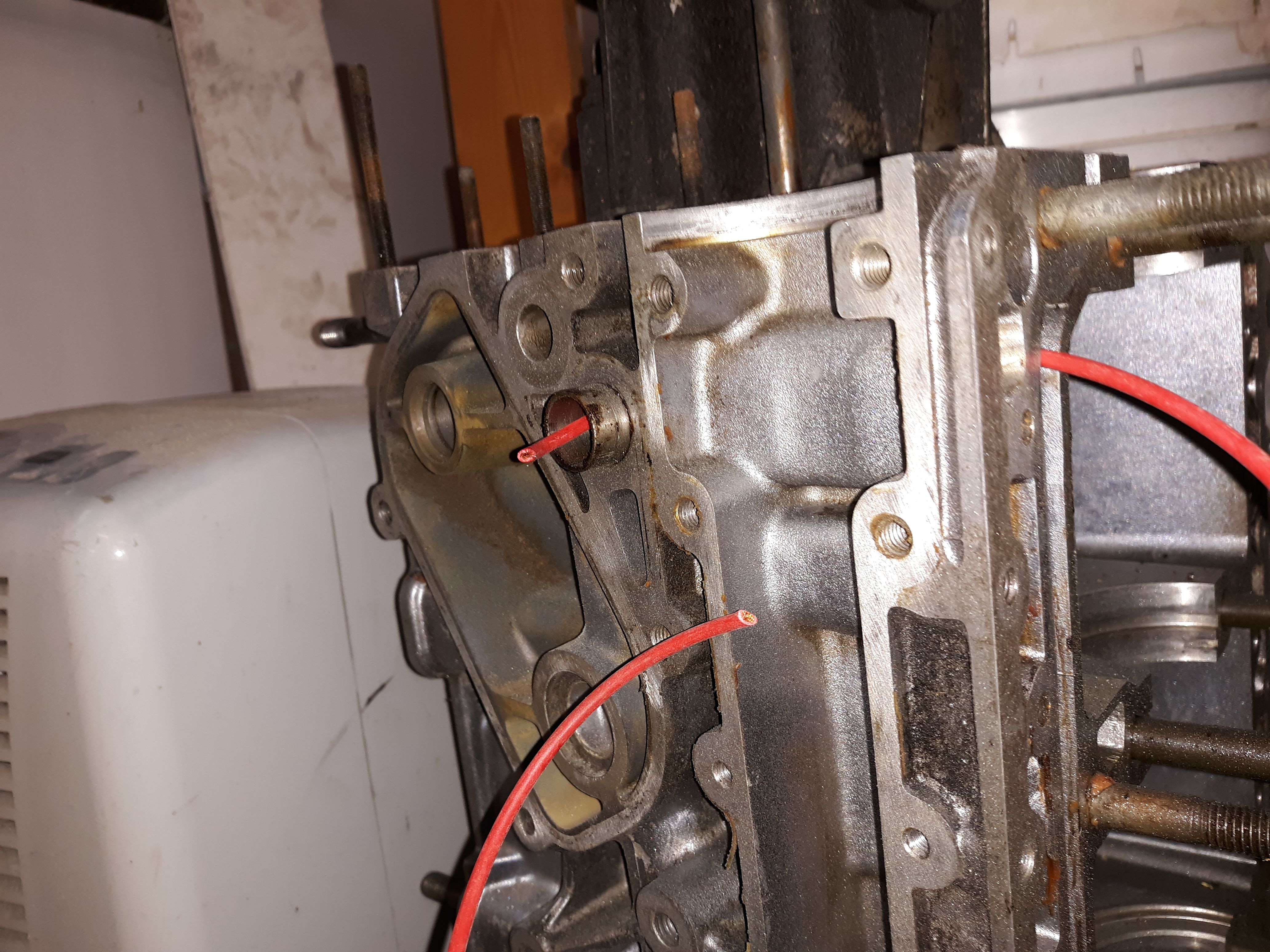
The short red wire is coming out of the hole (upper left) where the OPRV is installed. The long wire (upper right) is coming out of the oil pump suction passage in the crank girdle.
The OPRV has a small piston that is held closed with a long spring. I checked the spring force, very crudely using a kitchen scale, and measured 5 pounds of force. The diameter of the piston is 0.4″. Doing the math, the force to move the piston is only 40 psi. This may explain why I was getting 3 bar! I neglected to measure the spring force on my new valve, which I bought from Travis at Rennbay, but as I said it fixed my problem.
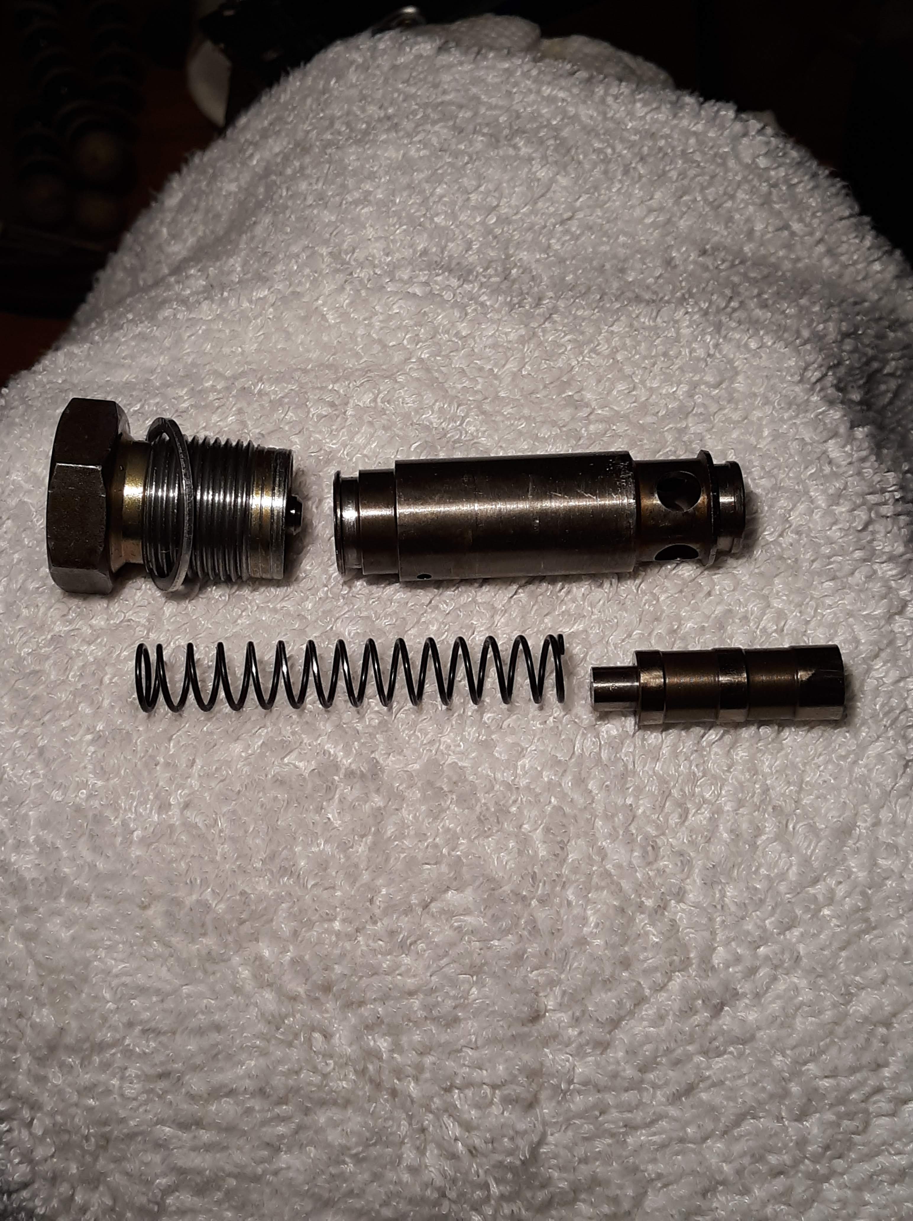
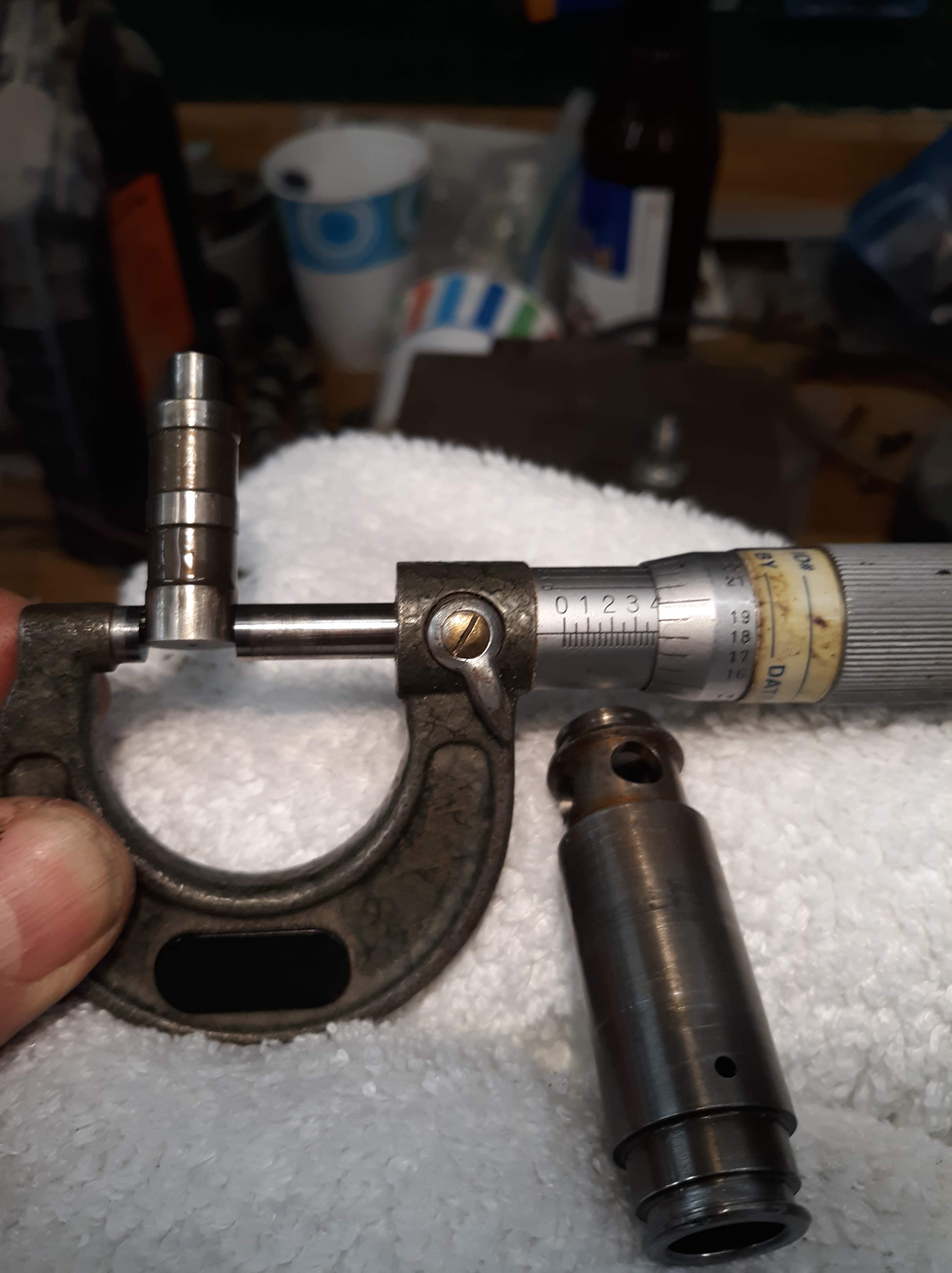
Piston diameter = 0.4″
The piston fits inside the outer sleeve, shown above on the right. When the piston moves back into the sleeve, it starts to uncover the 4 round holes. This opens up a flow path, as noted above, which leads to the oil pump suction. I have posted a couple of Youtube videos below. The longer one shows me depressing the piston with a nail, opening the round holes. The second one shows that the far end of the OPRV is slightly spring loaded. I think this mainly serves to allow for small amounts of differential axial expansion due to heating and cooling.
Many folks worry about alignment of the valve. More specifically, one must align the cooler housing correctly when installing it. There isn’t much wiggle room on the position of the cooler housing. And for the 1 piece valve, the external housing doesn’t move, just the piston inside. So I suspect you can get away with doing a visual alignment. But to be safe, I bought and used the alignment tool.
Folks talk about the valve sticking open and causing a total loss of oil pressure. I guess it could happen, for a valve in very poor condition, coked up with deposits, etc. But it would be a hard thing to prove unless you were to remove the valve and see the piston compressed with the little holes visible. Same story with it sticking closed.
The Porsche OEM valve is very expensive but then again it is a precision device with bad consequences if it does not work right. The one I got from Rennbay seems to be working fine and is less costly. It only fits the 87 and newer blocks.
So who knew there was so much to know about the 944 oiling system. Knowledge is power.


Update: Here is a tip from Michael Mount:
When rebuilding a 944 engine I always disassemble the oil pump to inspect the housing and gears. When reassembling, coat the gears and housing with white grease (it doesn’t take much). The grease closes up the clearances and maximizes the ‘suck’ to pull oil up the pickup tube. The result is oil pressure without the mess or headache when there is none.
MM
PS: You’ll need a hand held hammer type impact driver to disassemble the pump (cheap) and 574 to reseal the pump housing. You’ll see where the factory sealed it, so just duplicate what they did.
Update: This link was posted to Rennlist. It takes you to a Clarks-Garage discussion regarding resistance values for the oil pressure sending unit and a way to test the circuitry downstream of the sending unit. Brilliant!

Many thanks for this explanation. I have problem with my 84´ Porsche 944 N/A. Every time when I stop my car for some hours, it takes very long time to build up the oil pressure when I start it again. Something like air in oil pump or like hot oil go back from pump to oil pan. Once it reaches oil pump again, oil pressure jump to 5bars and there is no problem with pressure until next stop longer than two – three hours.
Relief valve works fine, oil is 20W-50 and oil filter is new and correct type.
Do you have any idea what else can it be?
Many thanks in advance
Posted by Vit Holkup | August 2, 2013, 11:48 amHey Vit,
You should have received a reply from me, from harvey.ferris@gmail.com
Harvey
Posted by newhillgarage | August 4, 2013, 2:35 pmHello Harvey,
Great job in explaining this oil system. I have been wanting to tear down an engine to really understand this system, but I don’t seem to have the time to rip my engine out to do so.
I rebuilt a dead 1986 944 NA engine (dead from a #2 bearing spinout on a race track… I guess the guy didn’t have the proper oil level and when he was in the long turns, the oil moved away from the pickup due to centrifical intertia and the first thing to go was the #2 bearing due to oil starvation).
For my rebuild, I chose to do 2 items that are intended in minimizing this from happening (at least according to everything I have read and recommendations to me on my new purchase).
1) Install a freshly rebuilt crank that has been cross-drilled
2) Install an oil pan baffle that keeps the oil fluid (without air) and near the pick-up tube.
I have rebuilt engines before on occasion, but I must have done something wrong as I have 2 problems that I am concerned with. Here they are:
A) I have exactly the same issue as Vit above and it seems like my pressure takes much too long to build up upon a fresh start (after sitting for many hours and cooling down)
B) After a cold start, and I finally get decent oil pressure, the pressures seem to be normal until the engine is warm or hot. At this point, my idle oil pressure starts fluctuating rapidly (bouncing between almost nothing and normal idle pressures).
Do you have any suggestions on where to start looking to really understand these issues? For point A, perhaps you could either post or email me the comments you sent to Vit?
As for item B, the warm/hot idle oil pressure gauge fluctuations, I am at a loss as to what to do to correct this. After the rebuild, I did a low hour oil change and decided to put in a heavier oil to see if this could reduce or eliminate the fluctuations and it almost has eliminated it. This was a while ago (and I have not been driving it… probably less than 500 miles or so since the rebuild), but I think I used either a straight 30W or 40W. Before I really start driving it, I want to figure out why the fluctuations are happening and make sure I am running the right weight oil.
If you or any others with either great knowledge or experience could give me some suggestions, it would be greatly appreciated.
If the oil pan on this car was not so hard to drop, I would inspect the oil pickup tube assembly and make sure that there is no chance of a leak and air getting to the pump (but for those that know the 944, this is an engine removal job… and at this moment, I don’t have the time to jump into this one). I don’t believe the fluctuations are gage related as running the engine with a higher viscosity oil, the warm/idle oil gage fluctuations almost disappear… so these pressures of the gage appear to be what is really happening in my engine.
Thanks for any assistance anyone can give,
Brett
Posted by brettob | August 31, 2013, 11:57 amHi Brett,
If your oil comes up to pressure slower after a long time between starts, I would say the problem is most likely a small leak in the suction side of the pump that breaks the vacuum and allows the oil to drain back into the pan. I guess the same thing could happen on the pressure side. It could be a bitch to find the leak, unless it is in the oil pickup tube itself, which has a history of cracking. I have gotten in the habit of sucking it up and paying Porsche for a new pickup tube when I do a performance rebuild. I have also had 2 rebuilds where the Locktite based seal at the crank girdle or the oil pump was faulty, as in I did a poor job with the seal 😦 That resulted in no oil pressure at all, as the pump would not prime.
Regarding the pressure fluctuations, I would still recommend that you positively rule out the sending unit, wiring, and gauge. In particular, the wire from the sending unit to the guage could have compromised insulation (due to its harsh environment) and may be “fluttering” against a ground, give you a strange reading. It’s a hassle but installing a temporary mechanical guage as a check might save you chasing other phantom causes. If you have a good voltmeter with a high sample rate, you could check the output of the guage directly and see if anything weired shows up. Even a cheap analog meter should be a to mimic the oil pressure guage needle movement.
Posted by newhillgarage | August 31, 2013, 12:38 pmBefore starting my career in the Porsche world, I was a “chevy teenager.” I gound cranks in a big high volume machine shop. I followed Smokies info that was in print alot. I do not disagree with your line of thinking. However, I really believe if you look at other crankshafts and the oil “timing” where it feeds the rod bearing compaired to the compression hit you’ll see that the crank gets it’s shot of oil 90 degrees before. This is not so on other peformance engines. Also as you stated, the oil has to make a 90 degree turn inside of the crackshaft. While, the engine is turning in the same direction. This doesn’t make since as under such high rpm the oil really doesn’t want to go out of that hole. When someone cross drills the crank in my opinion, they are really doing an injustice to the crank as then the oil does like electricty and follows the path of least resistance and feeds the rod journal after the compression hit.
I would ideally like to see the oil galley for the rod journal redrilled to feed just barley before the compression shock.
I have had that done on several 944 builds ad I beleive it helps. I cannot disagree with your line of thinking as to aeration. I just thought this should be considered to.
Jim
Posted by Jim | March 8, 2014, 1:24 pmHello Jim, I like your thoughts on the placement of the cross-drilled oil hole placement. Seems to make sense to a non professional (but a mechanical engineer). Too bad I already had the standard cross-drilling done or I would have considered this. I would guess that since I don’t race my vehicle, it probably shouldn’t hurt it (plus lots of people are running around and racing successfully with cross-drilled cranks.
I don’t know if you read my post above yours, but do you have any thoughts on the problems I am experiencing? I still have not torn into my engine since the post due to lack of time (I usually am traveling for a living… so rarely at home for any length of time). In fact the car only has a few hours on it since my original post.
I am wondering if you or anyone else can think of a clever way that I can figure out (or test) if my oil gage fluctuations are due to a pre-oil pump vacuum loss situation or a post oil pump pressure loss situation without taking the time to remove the engine and tear it down. Because I have the delayed oil pump pressure, I think there is a sad chance that I might have a very small leak in the oil pick up path somewhere. It is not near as bad a Vit’s is in the early post, but if mine sits for a few days or so, then the oil pressure build up is delayed by 5 seconds or so. But, any restarts while still even partially warm or a day later don’t seem to do this.
For my problem A) {delayed oil pressure after a few days sitting}, I was thinking it would be interesting to come up with a way to isolate the suction side of the oil pump feeding gallery without removing the engine. Then I could connect a suction pump up to this oil galley and pull the oil out of the pan with the external pump. If I then saw bubbles in the oil being sucked up, I would know my lower side had a small leak. Then perhaps this small leak could also be creating gage fluctuations because when the air gets to the gear pump, then the air compresses and the pressure drops. But maybe on higher rpms, there is not enough time for enough air to get in the system and the gage stays steady. I don’t remember what the oil pump structure looks like, so I am not sure if there is a practical or possible way to do this type of test. Or… if there is any easy way to get the pan off for an inspection without taking the engine out.
As for my problem B) {fluctuating oil pressure only at idle when hot}, I was thinking that 4 possible things could cause this. Because it fluctuates at what I would think is something related to engine rotations or speed, the pressure must be lost (or not created) during a certain rotation point of the engine. 1)The first thing that comes to mind is a problem with the oil gear pump. If there was a tolerance problem somewhere, maybe it loses some pressure, but I have records from the previous owner that it was replaced by the Porsche dealer just a few thousand miles ago and when I did the rebuild, it looked like a new pump… so I didn’t replace it. 2) The second thing could be the camshaft and a bearing??? I am thinking that when the cam rotates, if for some reason there is a location on the rotation that provides greater oil gap area between the bearing and the cam, this could drop the pressure. On my rebuild, I did what I would call a “short block” rebuild because the previous owner had also recently done a top end job. So my rebuild was crank, bearings, honing, rings timing belt, etc. 3) The third thought is a similar oil gap problem on the crank shaft. I suspect that this is the least likely item as I used plastigage and measured all of these clearances prior to assembly. 4) The other possibility is related to problem A) {delayed oil pressure at cold starts}. In this case, my theory is that the air being introduced into the suction side of the oil galley before the pump is causing the pump to lose pressure due to the air bubbles being introduced at slow pumping speeds. Any thoughts on a practical way to check for 1), 2) or 3) above? My crazy thoughts are that it would be nice to introduce oil pressure and flow through the system after the oil pump (with the original oil pump doing nothing at this test). Then if I put 30 -50 psi of oil pressure and flow on the system, and then cranked the engine at starter speeds, I could watch a gage and see if the pressure stays steady or if it is dropping due to an excessive clearance on some rotational part (ie the cam or crank). But again, these seem to be partly crazy thoughts as I am not sure of a simple and practical way of doing this.
Any thoughts from any of you guys or gals out there would really be appreciated.
Thanks, Brett
Posted by Brett | March 9, 2014, 1:54 pmI am experiencing the exact symptoms as Brett describes above, wondering if this was ever resolved?
Oil pressure takes 5 seconds to build when cold, and fluctuates slightly at idle – worse with thinner weight oil and also, strangely, when pointed uphill.
I have assumed this to be an issue related to the pump or pump sleeve, which I understand to be a “friction” fit. I’m probably due for a front-engine reseal this year, and I’d like to have all of my bases covered is there was a solution that Brett discovered?
Posted by Adam | March 15, 2021, 12:13 pmFrankly, 5 seconds does not sound alarming to me. Neither does the flucuations at idle. If my car has sat for a while, it takes 2 0r 3 seconds for the oil gauge to reach a final number. And remember. The sending units and gauges, which can now be 30 years plus old, can get wonky. The “friction fit” is true and is controlled by the large torque on the nut on the front of the crankshaft. If this nut is coming loose, you will have much more dramatic symptons!!!
Posted by newhillgarage | March 15, 2021, 1:45 pmThanks for the quick response Harvey. Very much appreciate your contributions to the 944 community.
Posted by Adam | March 15, 2021, 10:23 pmThank you for a brilliant explanation on the oiling system.
I’m going to add something that is standard knowledge in high level motorsports for over 20 years now. Cross drilling is no longer done in OE engines anymore. The world’s best crankshaft manufacturers do not offer cross drilling either.
Porsche people as a rule ignore all advances in motorsport and engineering. Well, New GT3s and Caymans are now straight shot oiling in the crankshaft as well.
It’s simple logic, the pressure is fed into the main and straight shot oiling is the ONLY solution because centrifugal force forces the oil to the radius of the crank throw. Forcing it to make a 90 degree turn when it wants to go straight to the top of the throw on the rod journal counteracts the natural centrifugal force and actually exceeds the system pressure at higher rpm. The only way a crankshaft should be drilled is from the top center of the throw in the rod journal straight through the web out the opposite side of the main journal. The main is under pressure and not subject to the stroke radius. The rod journal oiling hole is always at the highest point of the stroke radius. This actually aids bearing oil flow with higher rpm. That’s why cross drilling is no longer done by any manufacturers or motorsports. The permanent fix for any 944 is to plug all the holes in the crankshaft and drill it directly from the top of the throw rod journal center through the web and straight out the opposite side of the main journal center. Every main journal feeds a single rod journal. There’s no room left for argument here. Cross drilling went away a long time ago. It’s the example of what not to do of many engineering documents from 20 plus years ago.
Posted by Kurt Emerson | August 18, 2022, 4:43 amHi Kurt, thanks for your input. I always thought that adding extra holes to the crank was wrong headed. I hope my article doesn’t imply otherwise.
Posted by newhillgarage | August 18, 2022, 11:40 am