I’m in the middle of rebuilding the engine for my track car. I decided to pull apart the oil pump to clean it up and inspect it. Since my previous article Porsche 944 Oiling System Explained has been one of the most popular articles on my website, I decided to add the following discussion of what I found with the oil pump.
Let’s start at the beginning. Oil is pulled from the sump via an intake structure which is submerged below the normal oil level in the oil pan.
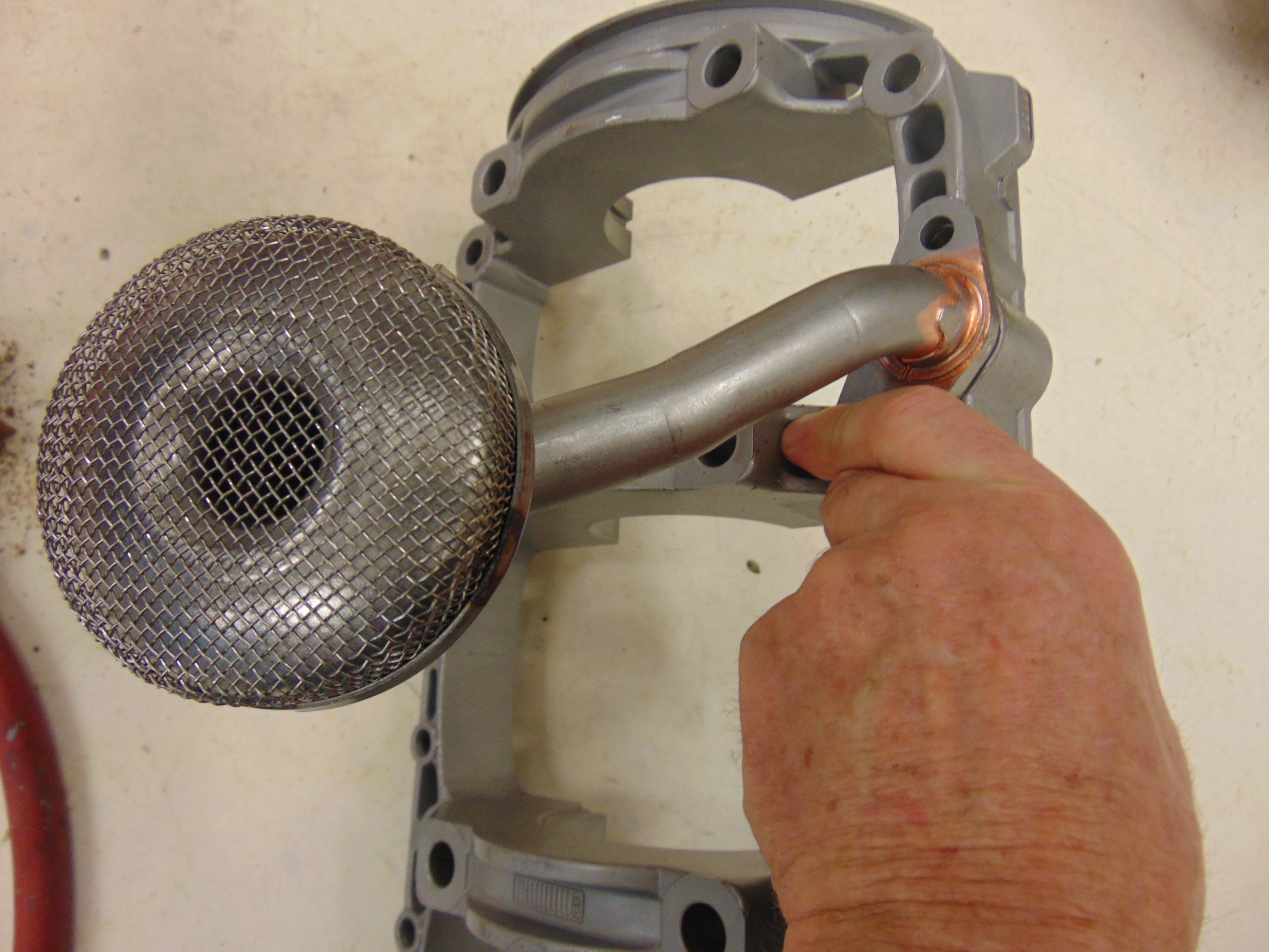
Oil pickup tube, with screen.
BTW, the pickup tube shown is a brand new OEM piece and is being held into position on the crankshaft girdle. I wanted to install a new pickup in my track engine, as there is anecdotal evidence that the weld at the tube to its fitting can fatigue and crack.

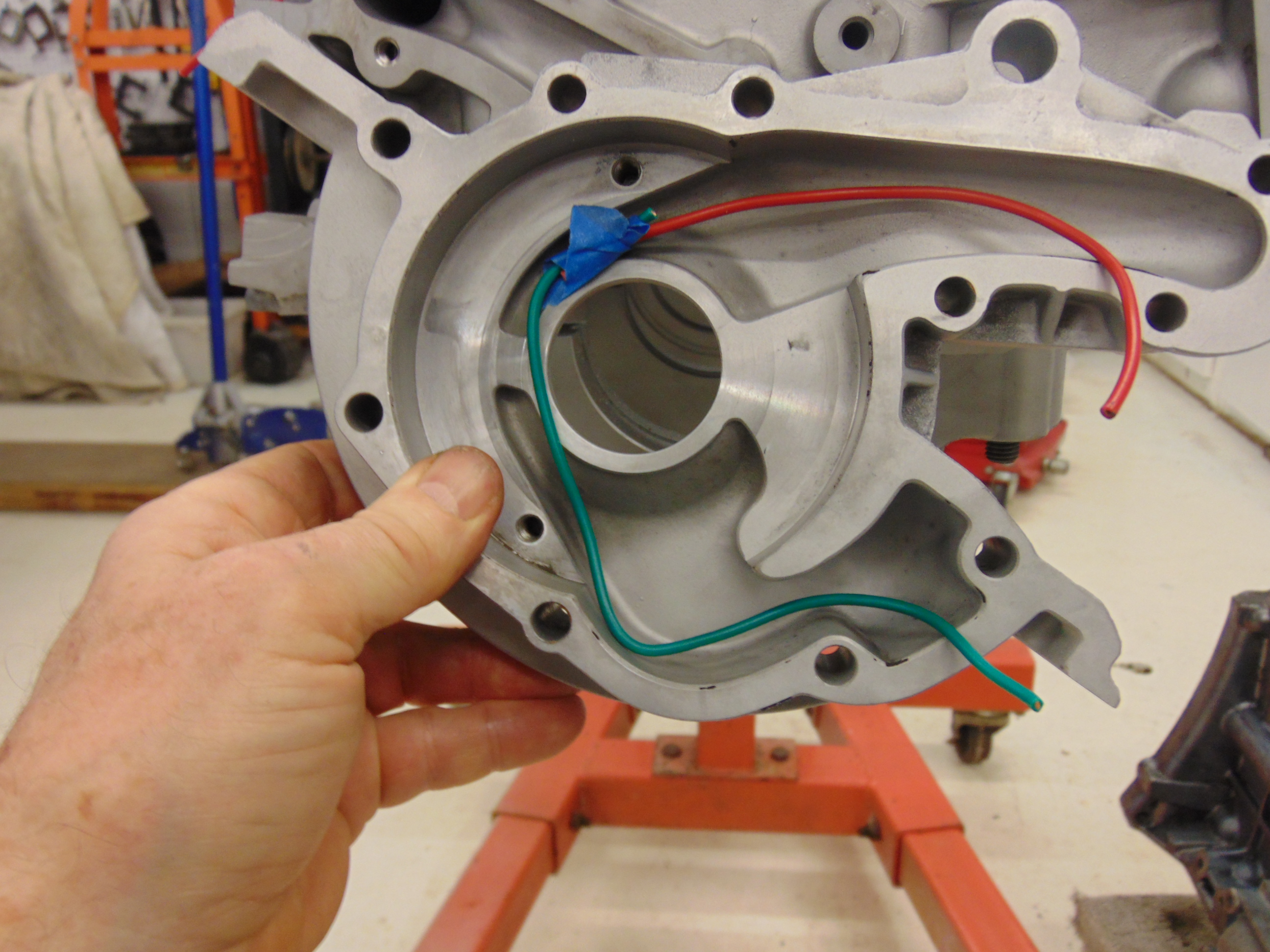
A further view of the crank girdle, showing the passage way that leads forward to the oil pump.

Oil passage way in crank girdle.
The above picture shows the passage way machined into the crank girdle. This passage leads forward to the front of the block, where the oil pump is mounted. This passage way is hermetically sealed against the bottom of the block. You can also see the 5 mounting points for the crankshaft bearing shells.
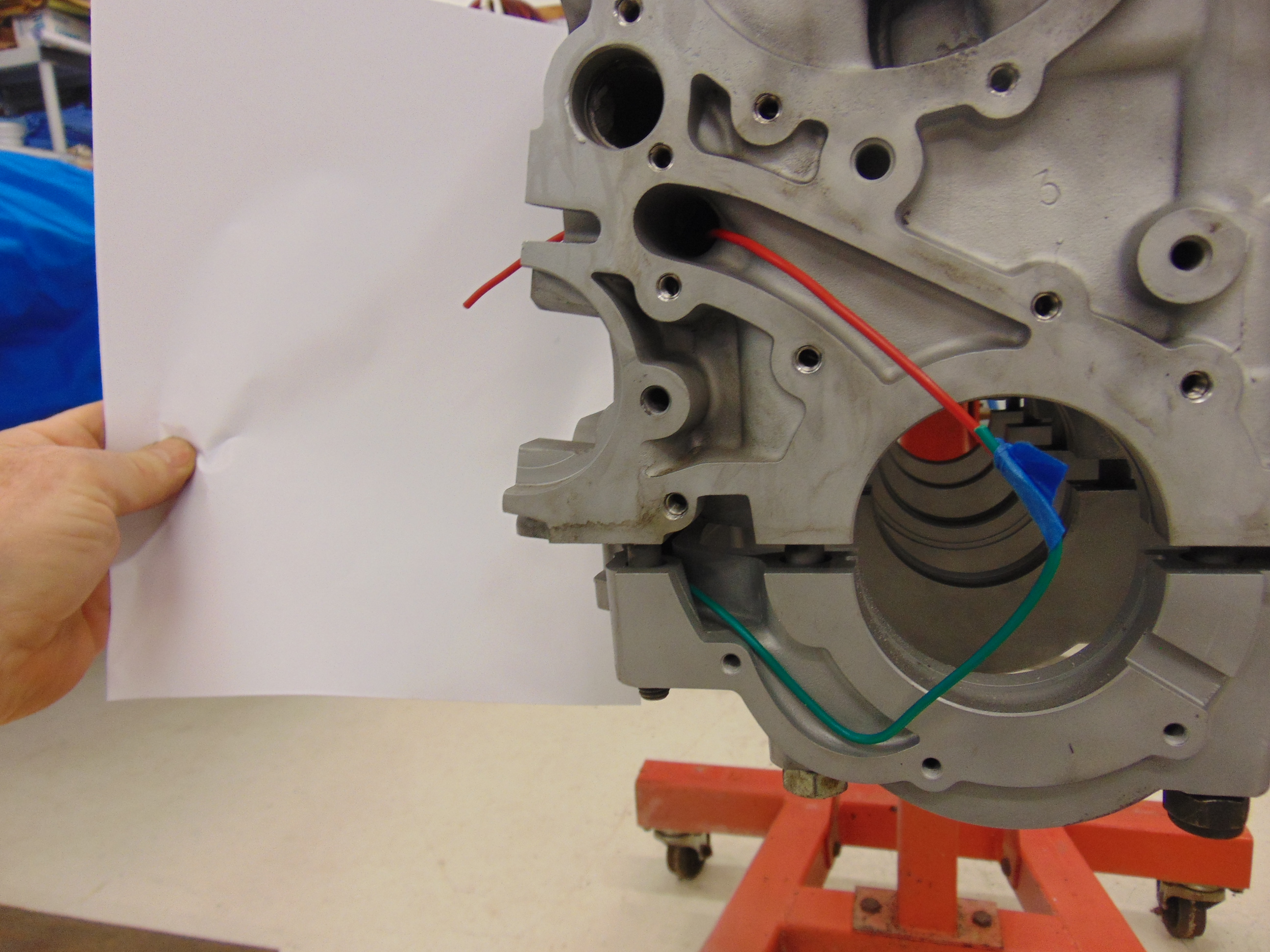
Green wire- oil in. Red wire – oil out.
So here we are getting close to the actual oil pump. In this picture the crank girdle is loosely mounted for the photo, with a gap with respect to the block. The green wire on the lower left is emerging from the opening from the oil passageway. This is the oil suction point for the pump. The pump will eject pressurized oil at the point where the red wire starts. As we will see in the following photos of the oil pump, the oblong opening in the block is matched by the pump exit. The red wire emerging from the left side of the block is from the opening where the oil pressure relief mechanism goes.
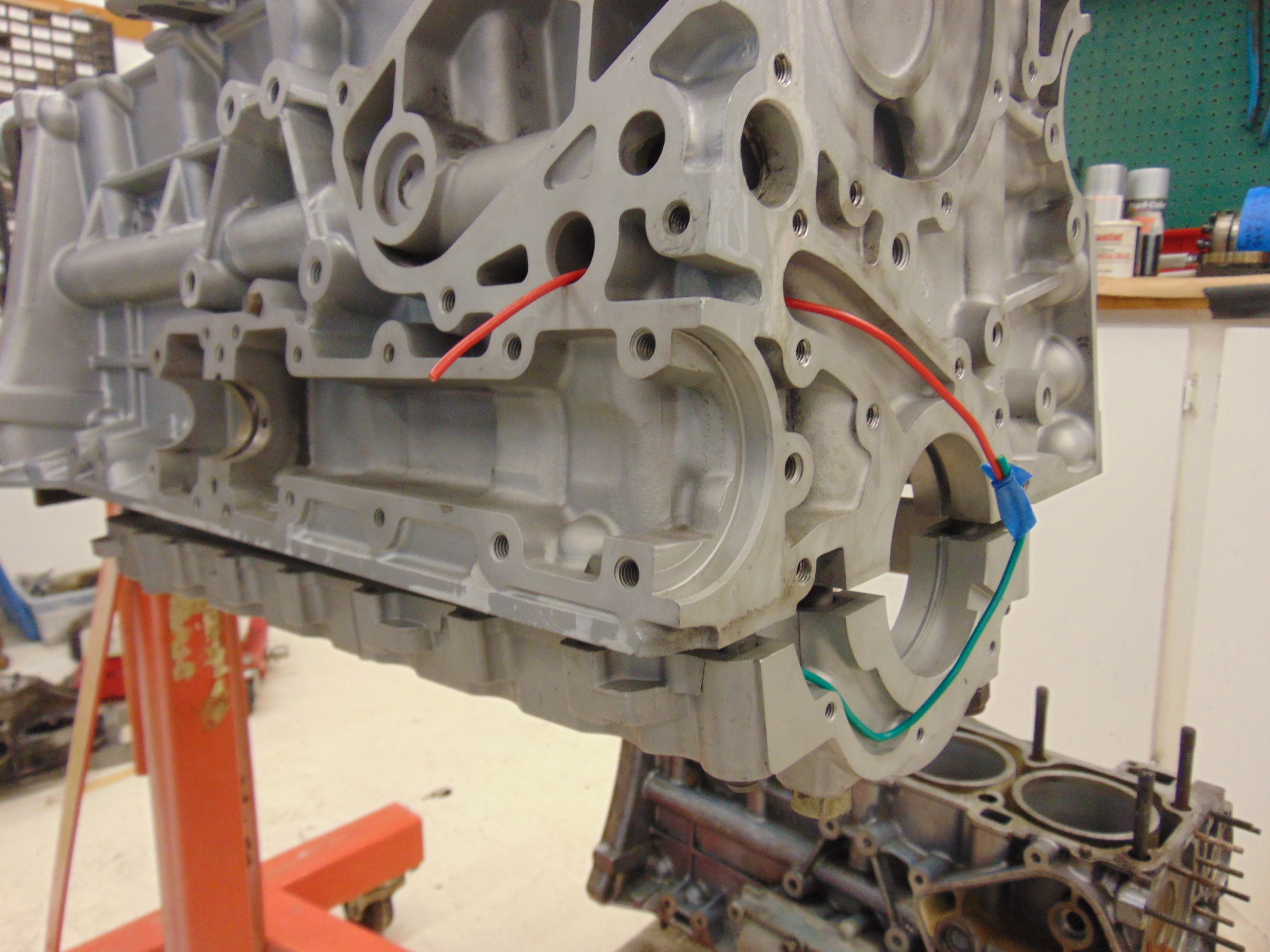
Above is another view of the same picture.

Oil pump housing.
Finally, a view of the oil pump 🙂 What an intricate and beautiful casting. The nose of the crankshaft will emerge from the hole in the middle of the pump.
Back side of oil pump. Impeller removed.
In this picture, I have simply rotated the pump to show the back side. As we will see, the important part, the impeller is removed. As noted before, the green wire is the oil in. The red wire is the oil out.

Impeller.
Here is the impeller, at least the side that you would see as installed in the pump. The business end is on the other side.

Impeller.
Here is the impeller. An interesting but simple mechanical pump. The center line of the inner gear with 11 lobes is offset from the center line of the outer housing. As we will see in the video below, the inner gear is rotated by the insert mounted on the crankshaft (in this picture held by my fingers, in the next picture mounted in place). The resulting motion gathers up oil at the 6 o’clock position, moves it up past the 9 o’clock position, and squeezes it out at the 12 o’clock position.
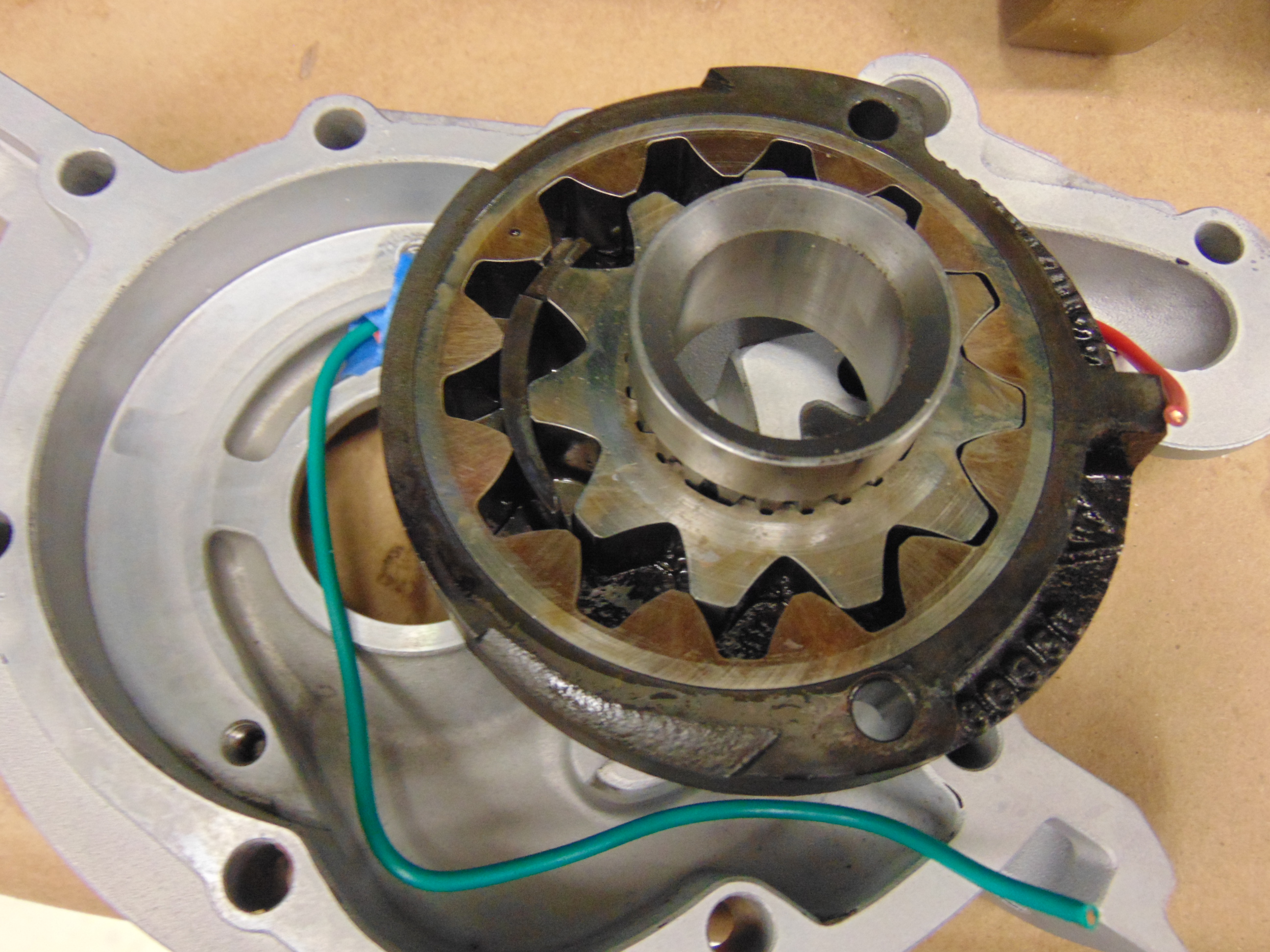
Impeller with crankshaft mounted drive gear installed. This drive gear is held in position by the torque on the large bolt at the end of the crankshaft. It is driven by friction. I suspect this is a failsafe. If the pump were to seize, the gear can slip before something more expensive breaks!
The above assembly gets flipped over, installed into the pump housing, and secured with two screws. Ready for action.
Here is a link to a short youtube video showing the impeller’s motion.
So where does the oil go from here?
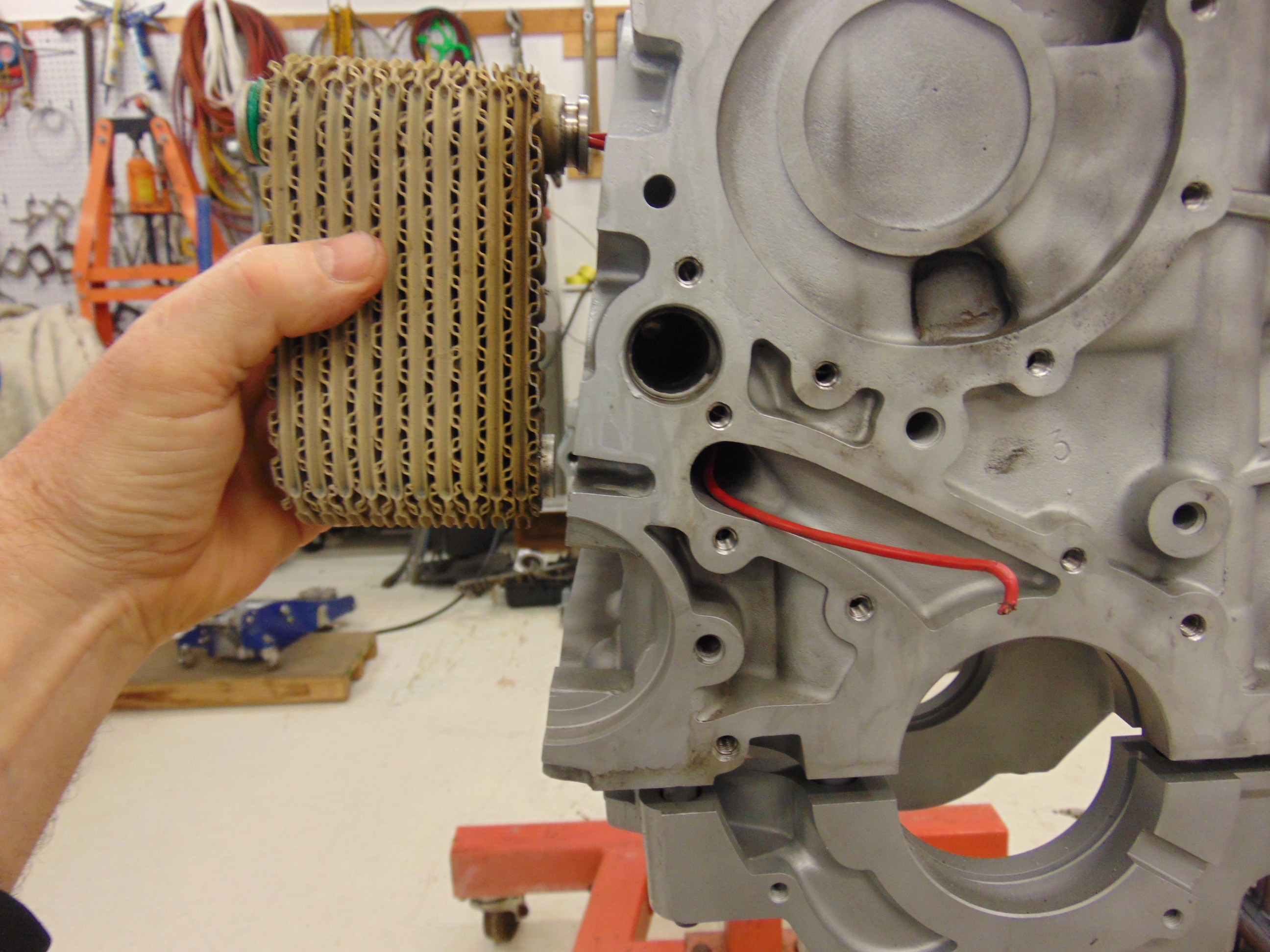
Water/oil cooler.
Well, the oil enters the face of the block and makes a 90 degree turned straight up, where it goes through another 90 degree turn and exits the block into the oil cooler element. This is a small radiator that has engine coolant on the other side. The heat of the oil is transferred to the coolant, to help maintain oil temperatures at at safe level. The oil emerges from the cooler on the opposite side (just above where my hand is).

Another view of the oil/air cooler.
The oil emerges at the connection with the green oil ring.
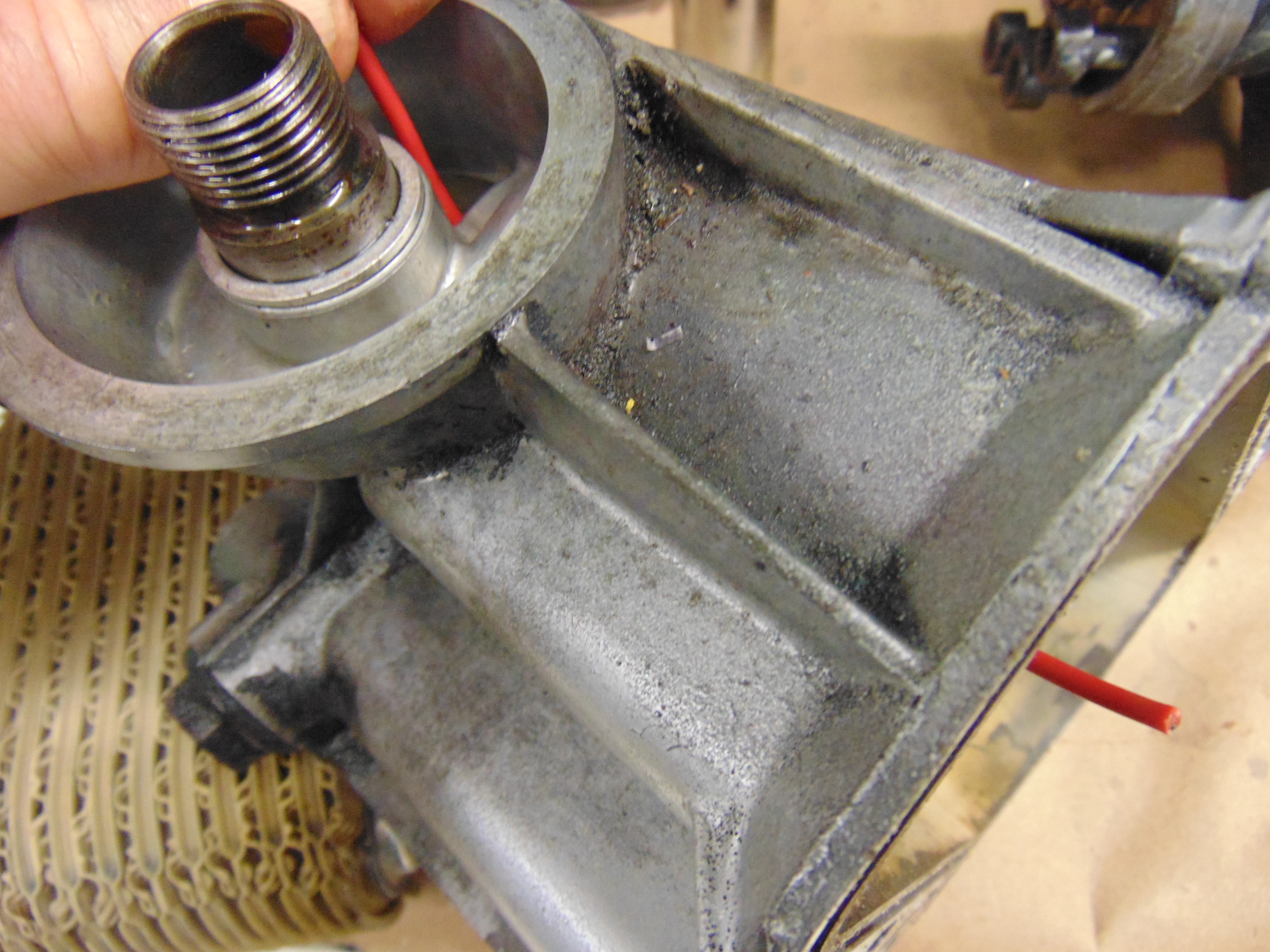
Here is the housing for the oil/water cooler. The oil from the cooler emerges in the opening where the red wire is coming out of. Interesting to note: if you want to “prime” your oil pump, you do not pour oil into the center opening where the oil filter screws on. You pour it in the opening shown with the wire.

Oil/water cooler housing.
And finally, the oil moves through the oil filter (not installed in this picture), out through the center hole with red wire, and back into the block. My previous article picks up at this point and discusses how the oil has a straight shot to the number 1 main and rod bearings but has to make several 90 degree turns to get to the number 2 main and rod bearings. See 944 Oiling System Explained.
I trust this helps you visualize how the 944 oil pump works. It’s really quite simple but very important.
So you may be reading this article because you have lost oil pressure. Here are some potential causes.
If you haven’t opened up the engine, then here are some likely problem areas.
- Your oil pressure sending unit has failed.
- The torque on the crankshaft bolt has relaxed to the point that the drive gear is not engaging.
- Your oil pressure relief valve has stuck open.
- You just installed a new oil filter. It is defective i.e. it is blocked. It happened to me once!
- One of the welds at your oil pickup tube has cracked. This breaks the suction on the oil pump and it will not prime.
- The oil/water separator has failed. If this happens, you should still get some pressure but your coolant will become oily very quickly.
- The oil pump has failed. Extremely rare.
In all of the above cases, the quickest diagnostic is to remove the oil filter and crank the engine. It will make a hell of a mess but you’ll know whether you are pumping oil!
If you have had work done on the engine i.e. you have removed the crank girdle, the most likely problem is that the seal of the oil passage way in the girdle to the block has a leakage such that the pump is sucking air rather than oil. You must follow the factory shop manual instructions exactly regarding sealing the girdle and the pump with the specified sealant.
Again, I hope this has helped. Oil is important. Keep it flowing!
BTW, the block, girdle, and oil pump housing have been bead blasted, which is why they are so clean. All the external surfaces were painted with a silver paint. Do not paint any surfaces that are exposed to oil or coolant or that are sealed with a gasket or sealant.
Update: Here is a tip from Michael Mount.
When rebuilding a 944 engine I always disassemble the oil pump to inspect the housing and gears. When reassembling, coat the gears and housing with white grease (it doesn’t take much). The grease closes up the clearances and maximizes the ‘suck’ to pull oil up the pickup tube. The result is oil pressure without the mess or headache when there is none.
MM
PS: You’ll need a hand held hammer type impact driver to disassemble the pump (cheap) and 574 to reseal the pump housing. You’ll see where the factory sealed it, so just duplicate what they did.

Discussion
Comments are closed.