So I’m in the process of rebuilding the engine for my track car and, as usual, I got sidetracked. As I was cleaning up the waterpump, I got to thinking, how exactly does this cooling thing all work? It turned out it was more complicated than I thought, with several interesting features. If you want to truly become a cooling system nerd, read on.
Note: The following addresses a cooling system for a 1984 car.
The Radiator
Let’s start with the radiator, which is the part most folks can see and understand best. The radiator is a water to air heat exchanger. It consists of many rows of small water filled tubes, with fins attached to them. The hot water passes through the tubes and dumps its heat to the air flowing through the fins. The fins provide a large surface area over which this heat transfer can occur. Modern radiators, including the 944’s, are made out of aluminum. Historically, radiators might have used copper or brass.
The tubes are supported at each end by header tanks. These serve to collect the incoming and outgoing coolant. BTW, for this article, coolant is understood to be a mixture of water and anti-freeze. The header tanks on the 944 are made from plastic. One header tank has an inlet connection for the radiator hose carrying hot water (upper left in the photo). The opposing header tank has a outlet connection that discharges the cooled water (lower right in the photo). On the 944, the header tanks are vertical and the tubes run horizontally. It is supported in a framework using rubber bumpers.

Note the blue fitting in the lower left corner. This is the drain plug for the radiator. They are easy to strip, being plastic. I keep several spares on hand. The electric fan assembly (removed for this picture) attaches to the 6 fastener locations shown. The temperature switch for the fans is the round black object on the left with two electrical connections.
I frankly was not sure what side was in and what side was out. A simple experiment determined what was what. I took my 944R out for a ride to get it warmed up. Then I aimed my infrared thermometer at the two hoses. The upper hose was a good 50 degF hotter than the lower hose. This told me that the hot water flows from the connection on the top of the cylinder head and the cooled water flows back to the connection at the water pump.

Hot water leaves the block via the upper radiator hose.
Cooled water leaves the radiator and passes through the lower hose to the inlet of the water pump.
BTW, you may have heard of getting your radiator “rodded out”. This literally means that the shop will insert a proper sized rod through each of the finned tubes to push out any gunk that has been built up. When radiators had metal tubes and metal header tanks, they could do this by heating up the header tank until the solder melted and disconnect the header tank, allowing access to the tubes. When done, the header is soldered back on. I had a Volvo 240 where doing this worked wonders for an overheating problem. But with modern tanks using a hybrid plastic/aluminum construction, they probably can’t do this. Fortunately, new radiators aren’t that expensive.
Radiator Electric Fan
The radiator removes heat from the system. I’m sure you know it works better when the car is moving. The radiator electric fan is there for those times when the car is moving slowly, in traffic. The fans are activated by a temperature activated switch mounted on the upper portion of the drivers side header tank. It is the device with 2 wires attached to it. When restoring my 944R, I found that both fans run at their highest speed when the fan switch reaches it temperature setpoint. A lesser known fact is that one fan will run at a much lower speed when you park a hot car and turn off the ignition. This serves to continue cooldown of the parked car.
Expansion Tank
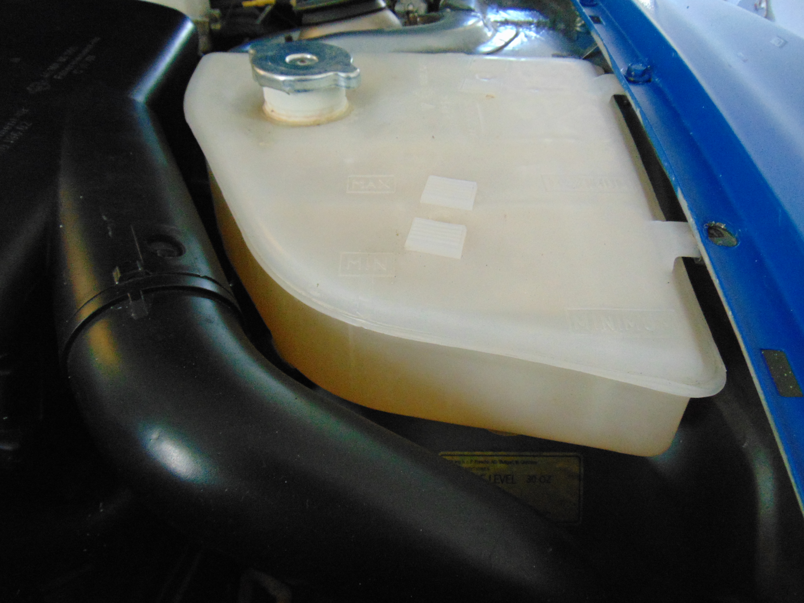
Expansion tank. This one is brand new. Usually, they are yellowed to the point where it is hard to see the actual coolant level. This can bite you if you let the car get low on coolant and don’t know it. Ask me how I know 😦
The expansion tank is the most visible part of the cooling system. It is mounted forward in the engine compartment on the left hand side. As its name implies, its most important function is to provide an air space above the level of the coolant in the tank. The coolant increases in volume as it is heated up. This increase in volume needs some place to go. This is accommodated by compressing the air in the air space. If you look at the tank it has a max and a min fill level. Keeping the coolant below the Max level leaves you a sufficient air space. Keeping the coolant above the Min level makes sure your system is sufficiently full. There is a pressure cap on the expansion tank. This cap is spring loaded such that it will bypass coolant when its setpoint pressure is exceeded. Typically 5 to 10 psi. This is a safety valve mechanism, to keep something more expensive or dangerous from bursting if the coolant gets exceptionally hot. As a rule, the cap should never release fluid. There are at least two exceptions that I can think of. If someone were to top off the coolant right up to the top of the tank, the next time the car was brought up to temperature, there would be no expansion space and the pressure cap would release. After enough fluid is expelled to accommodate the expansion, the cap would close. As a one time event, this is no big deal, as long as you understand what happened. Another scenario where the pressure cap may release is if it gets very cold and your anti-freeze is not up to snuff. Your radiator, being in the slipstream of the cold air, may freeze up. Then the coolant will overheat and the pressure cap may release. If this happens, you need to resolve the problem. And of course, if something bad happens to cause an overheating event, like a high speed run through Death Valley with an under filled coolant system, yes, the cap will release. If you dare to admit to watching NASCAR, you will sometimes see towards the end of a race a car running with a spout of steam coming out of the hood area. For some reason, they have boiled their coolant and are actively expelling steam through their pressure cap, maybe due to radiator obstruction or damage. They have made a racing decision to run the car till it blows up or they reach the end of the race!
There is an approximately 1″ dia tube leading from the bottom of the expansion tank to the right hand header tank on the radiator. This tube fills the radiator and the rest of the system. There is an approximately 3/8″ dia tube leading from the top of the expansion tank to the top of the left hand header tank. This tube takes air trapped in the radiator and routes it back to the air space in the header tank.
Filling the Coolant System
You add coolant at the pressure cap opening on the expansion tank. If the system is totally empty, this will fill the radiator first and then the engine. You will note that there is a right angle cast fitting that attaches the upper radiator hose to the cylinder head. It has two hex bolts that attach it and another hex bolt in between. You must remove that bolt to allow air trapped in the engine to escape during filling. I think you would also want to put your heater control slider in a “heat” setting in order to open the heater control valve. Even so, after you run the car a little bit, you may find more air has reached your expansion tank. As long as the coolant is above the Min mark, you are fine.
The Heat Source
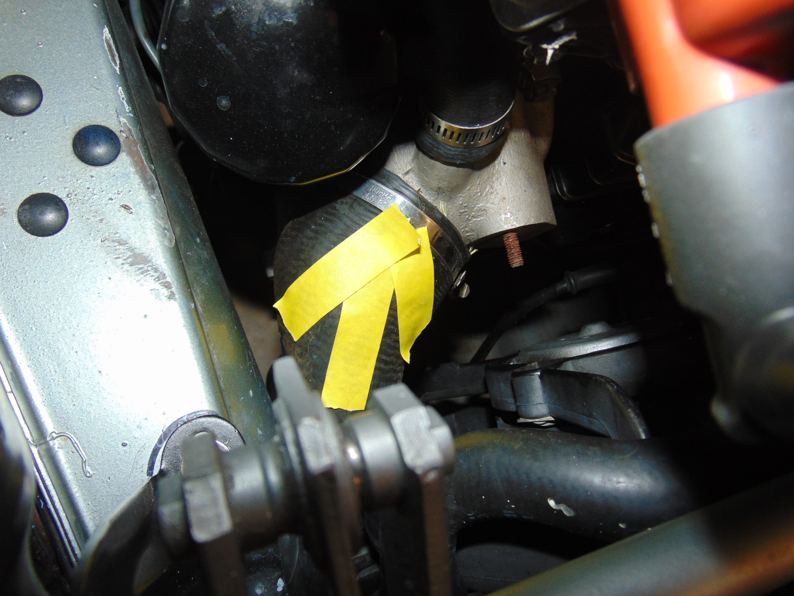
Let’s explore where this heated coolant comes from. That turned out to be very interesting, at least to a mechanical nerd like myself. You can see when you look at your 944 that the upper coolant hose is attached to a right angle fitting mounted to the top of the cylinder head. Where does this connection lead to? The pictures below will attempt to explain. The simple answer is that the hot coolant moves from the front of the block, past the cylinder walls. At the rear of the block, it does a U-turn and pops up through openings into the rear of the cylinder head. From there it moves forward past the combustion chambers to the front of the head, then to the right angle fitting, the upper hose, and the radiator.

Right angle fitting on the top of the block, where hot coolant is expelled. The hex bolt at the rear of the picture is the one you release when filling your system.

Opening in the top of the cylinder head where the hot coolant is expelled.
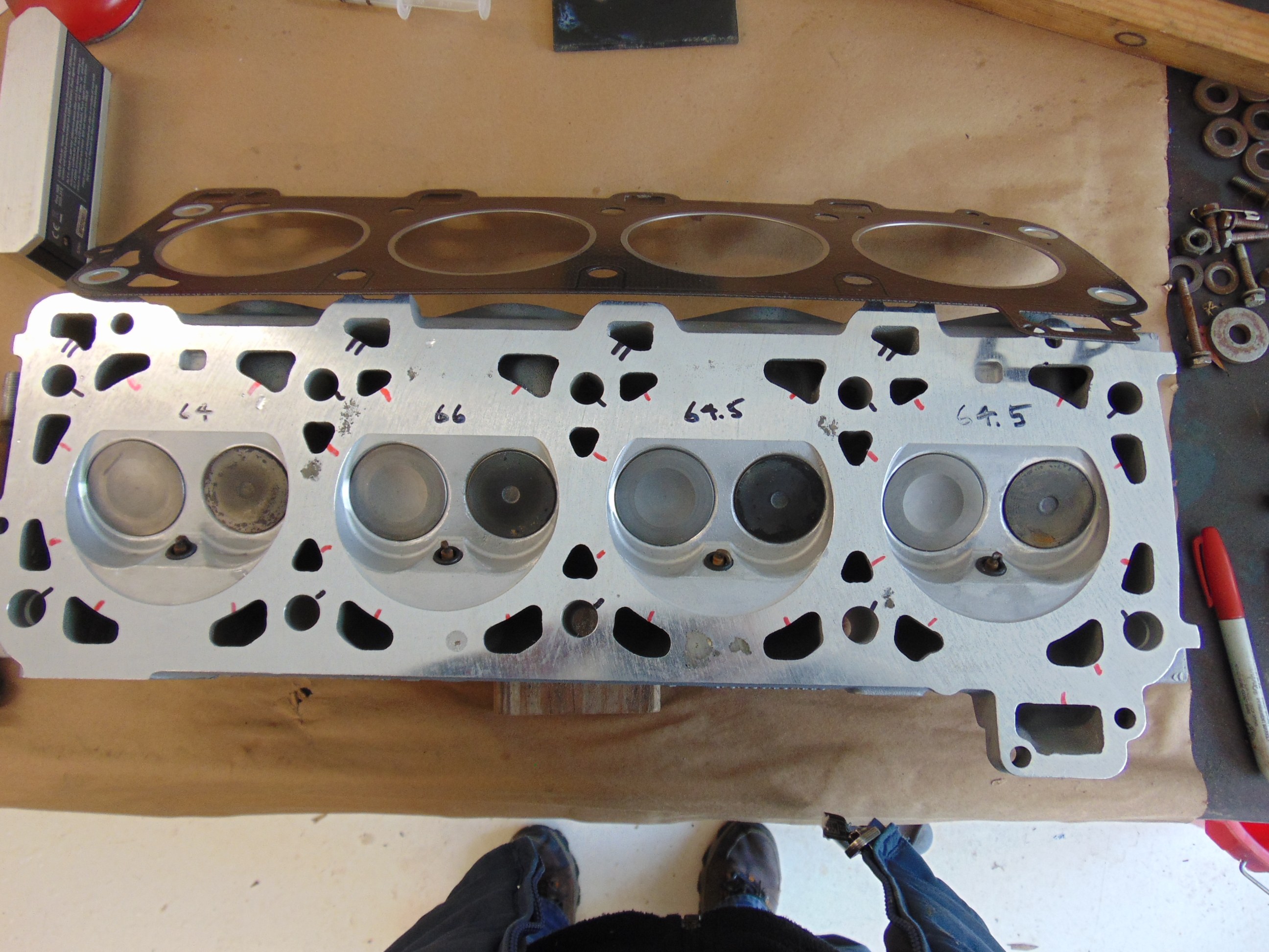
Cylinder head: Coolant passage openings are marked with a single red mark. Openings for the head studs have a single black mark. Oil return passageways have a double black tic mark.
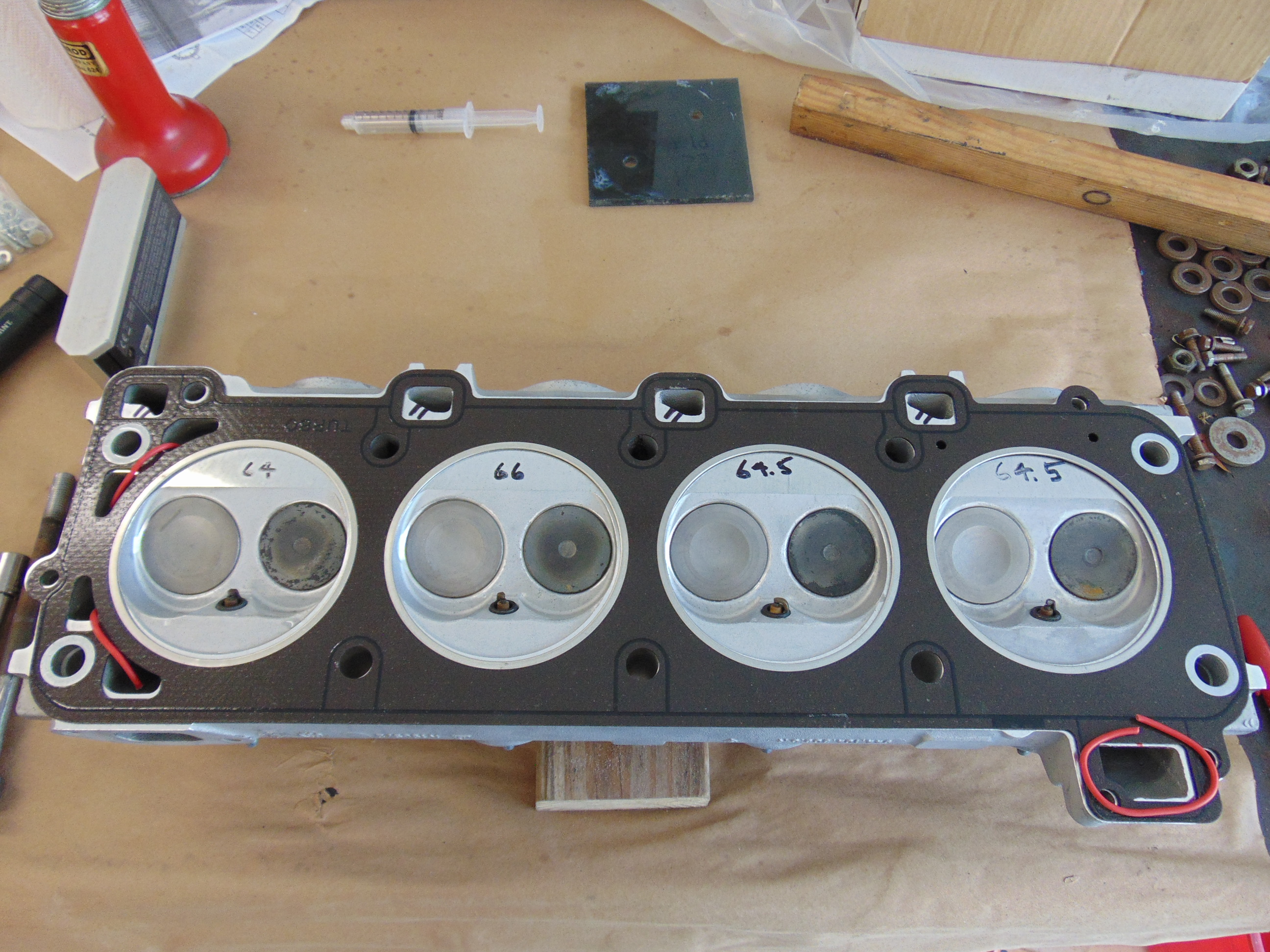
Head gasket applied over the cylinder head. It is seen that all of the coolant passages are blocked off except four openings at the rear of the engine (Left hand side in the picture). The opening at the lower right hand side is for the cold engine coolant return passageway.
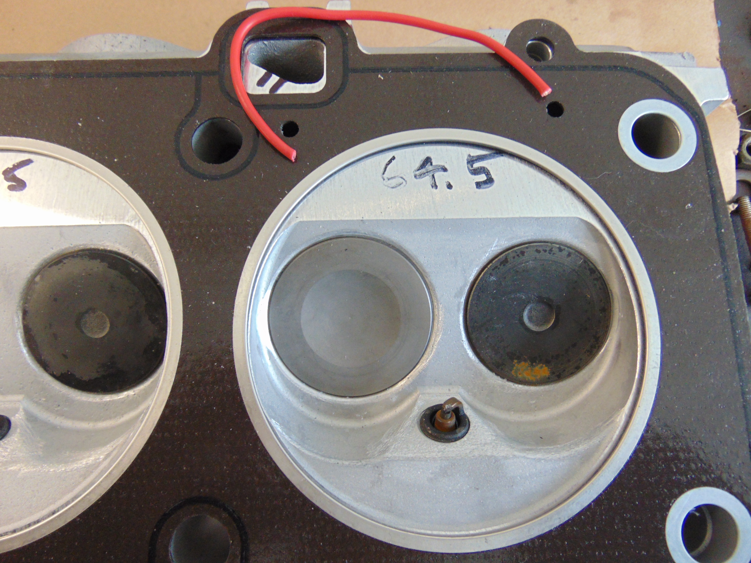
Interestingly there are two small holes next to cylinder 1. I suspect they allow a small amount of “short circuiting” to aid in rapid warmup of a cold engine.
Here’s a cool observation. As we see in the photos, there are multiple openings in the bottom of the cylinder head that lead to the coolant passages in the head. Yet we see that all but a few of these openings are blocked off by the head gasket. Here is what I think is going on. If you have ever looked at how castings are made, you will know that a mold is made out of sand. The molten metal is poured into the mold. When the sand is removed, you have your rough casting. I’m thinking that the head could not be molded with just a few passage ways. Instead, Porsche made it easy on themselves by having multiple locations where the sand has a surface on the exterior surface of the mold. Removing the sand after the metal is cooled is simple. Blocking the unwanted coolant passage is obtained via the head gasket. Very elegant. You rock Porsche!
The Water Pump
I have been working backwards from the standpoint of the coolant flow. Physics dictate that coolant flow goes from areas of high pressure to areas of low pressure. The area of highest pressure is the outlet of the water pump. The area of lowest pressure is the inlet to the water pump. I must admit that, after examining the water pump, I wasn’t exactly sure which side was the outlet and which side was the inlet. My experiment with the temperature gauge answered that question. The face of the water pump attached to the block is the outlet. The side with the hose attached is the inlet. That hose at the inlet of the water pump attaches to the outlet of the radiator, on the lower right hand corner of the radiator.

The outlet of the water pump pushes high pressure coolant into these 2 openings, which lead to the interior of the block.

Location on block where water pump is attached. Gasket in place, ready to accept the pump.

Water pump installed.
A cautionary tale: I had a bad day at the track years ago when I let the lower radiator hose get too close to the electric fans. It took about 3 laps for the fan to cut through the hose. Much steam came pouring out of the engine compartment. No, I wasn’t on fire, but it still ruined my day! So make sure you install and secure this hose with sufficient clearance to the fan blades.
We are almost done with the basics. The cooled water from the lower radiator hose is introduced to the inlet of the water pump. The pump increases the pressure of the coolant and blasts it through the block, around each cylinder wall. At the end of the block, the coolant makes a U-turn and passes forward over each combustion chamber. It exits the block at the front, on the top. It heads through the upper radiator hose to the upper left hand corner of the radiator. The coolant is cooled as it passes across the radiator. And repeat.
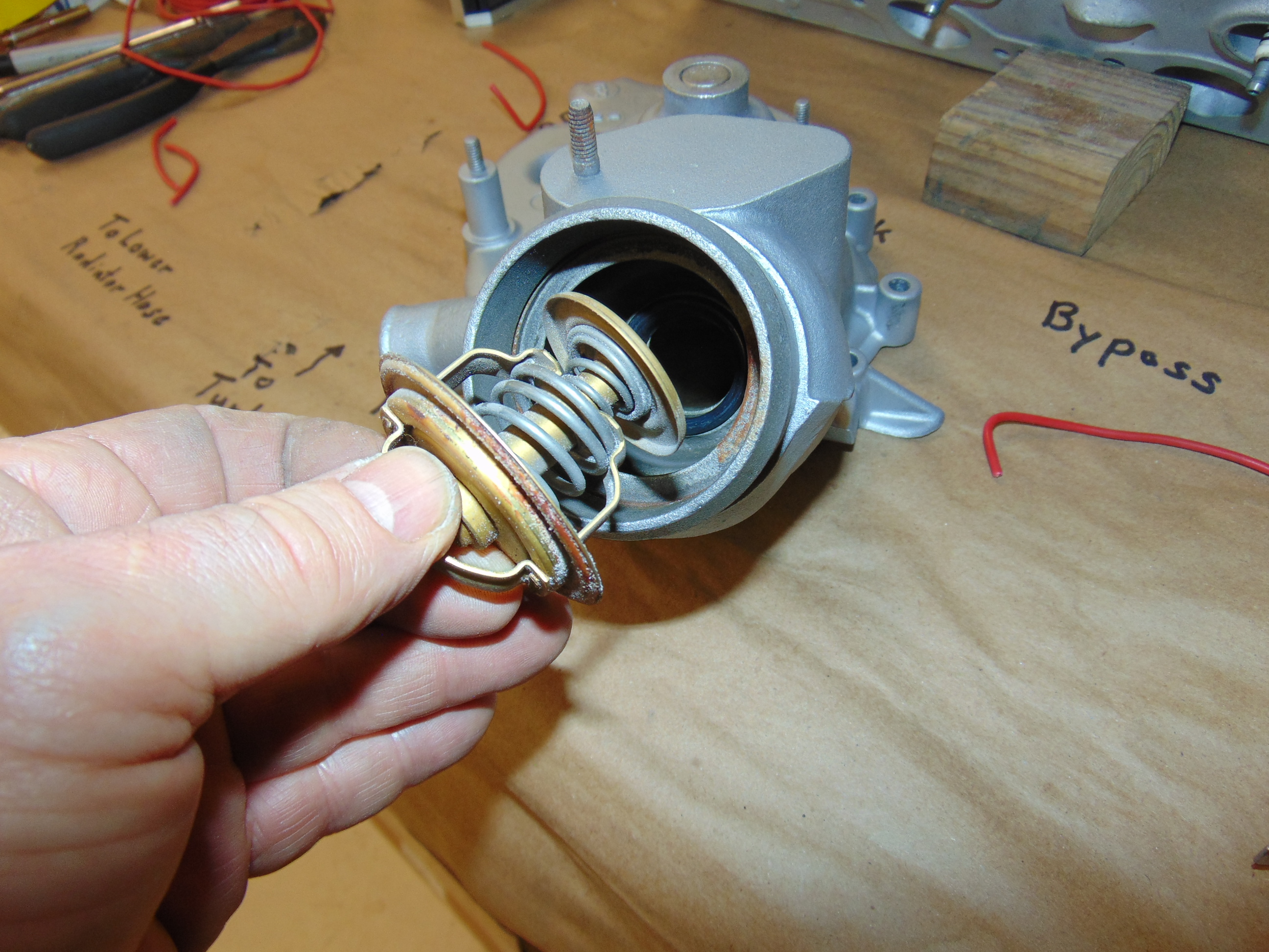
That is basically it. But there’s some interesting side action going on. Let’s look at the water pump a little closer. Nested in its inlet passageway is the poor mis-understood thermostat. The thermostat blocks flow from the outlet of the radiator until it reaches it’s setpoint temperature. My thermostat is labeled to open at 80 degC. When your coolant is below that temperature, the radiator is taken out of the action. So what happens? What happens is that the coolant flow travels through a bypass passageway. This allows a cold engine to heat up as quickly as possible. Once the thermostat is exposed to coolant above 80 degC, it opens up and allows coolant to move through the radiator. At 90 degC, it is fully open. Once that happens, the coolant flows through the radiator and is cooled. As shown in the photos, the bypass flow is taken from a point just below the right angle fitting for the top radiator hose. As the thermostat opens, the smaller disk shown in the photo below moves such that the bypass flow is cut off.
Thermostat
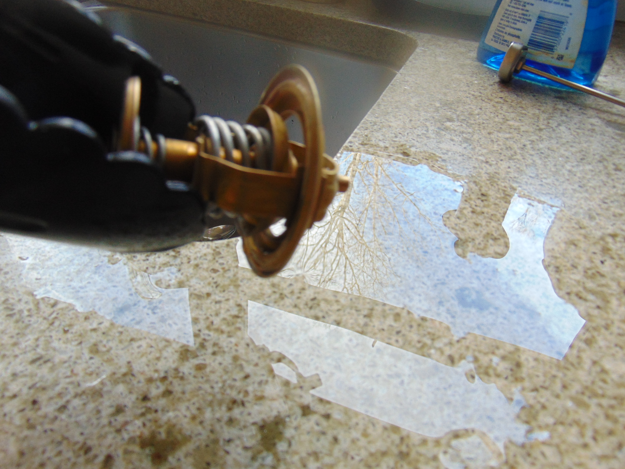
Thermostat just removed from boiling water, so that it is opened.
Changing your thermostat out for one with a different temperature setpoint is not a solution for coolant system problems. The setpoint (80C – 90C) is designed by Porsche to help your engine run at an optimum temperature for power, fuel economy, and emissions. Putting in a thermostat that opens at a lower temperature will not resolve problems such as a blocked radiator or failing water pump. Of course, if your thermostat is so defective that it is not opening at all, then yes, you will have overheating problems and replacing the thermostat will fix the issue. They are fairly inexpensive and a good “while you are in there” item to replace.
Another function of the water pump casting is to feed the cabin heater element. There is a fitting at the back of the cylinder head that, when the heater control valve is opened, moves coolant through the heater core. The return path is through a long metal tube connected on the passenger side of the cylinder head. The coolant flow from the heater is introduced to the water pump casting as shown in the picture below.

The various facets of the water pump are shown here. The “To Turbo” opening is blocked off for a N/A engine.
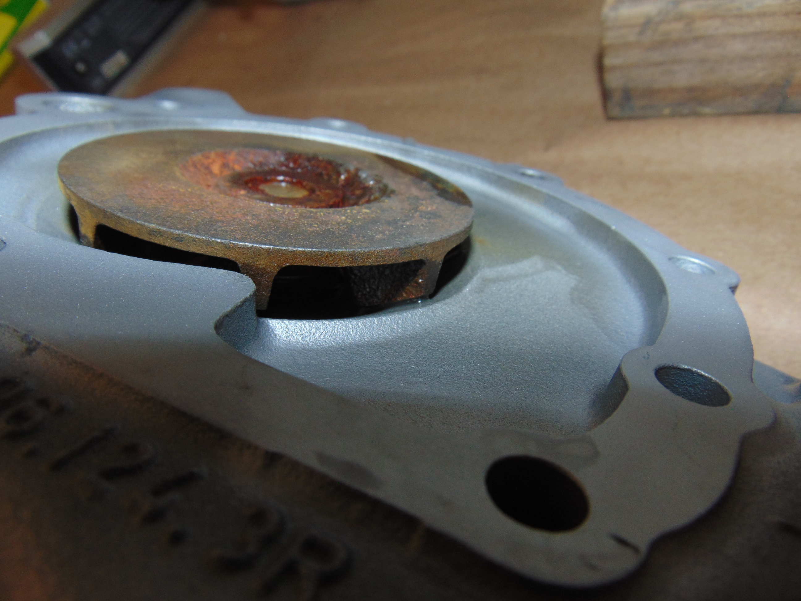
A close up of the water pump centrifugal impeller.
Another function of the water pump casting is to introduce coolant to the oil cooler mounted on the right hand side of the block. I found a small hole in the face of the block that introduces high pressure coolant into the oil cooler. The coolant passes through the cooler matrix, which is itself a small radiator. At the back side of the coolant, a larger opening returns the coolant to the block.

Oil to water cooler assembly. Coolant is introduced at the opening marked with the red wire on the right. It passes through the heat exchanger element and leaves through the opening shown with the red wire on the left.
Have we got all that? The water pump feeds coolant to the block, the heater, and the oil cooler. It bypasses coolant continuously and it also has a thermostat that opens after things get up to temperature. A tour de force indeed.
The coolant system has to operate over a wide range of operating conditions. It’s only active component is the thermostat. The remainder of the system operates through carefully selected openings and passageways. I suspect we never stop to think about the Porsche engineers who worked to bring this system together in form and function. Our greatest compliment to them is that we generally never give any thought to the way a Porsche 944 manages the ebb and flow of heat throughout its operating regime. As I’m sure I’ve seen written on a coffee cup “Happiness is a warm (not hot) Porsche!” Happy motoring.
Update 8/1/20 Here is a useful diagram posted by Rennlist Forum member Joeystanker


Discussion
Comments are closed.