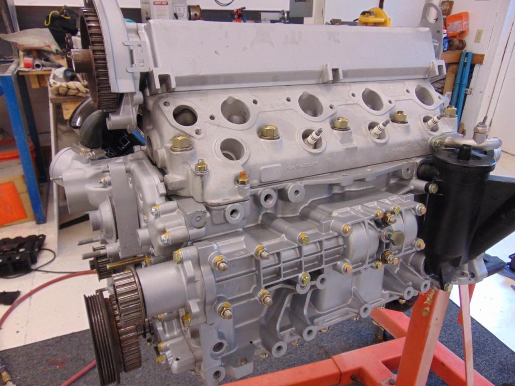
In our last article Part 3, we installed the cylinder head on the block. It’s really starting to look like an engine now. Now let’s talk about installing the cam tower. The cam tower is a little bit tricky only in that if you go about it the wrong way, you may bend some valves. That is because the 944 is an “interference” engine. This means that under the wrong circumstances, an open valve and a piston at the top of its stroke will try and occupy the same space, i.e. they interfere with each other. This happens in an instant, if the engine is running and the timing belt breaks. That is why there is so much discussion about replacing timing belts before they get enough age on them to break. The other circumstance is if you mate the cam tower to the block with things lined up incorrectly. If we are careful we won’t let that happen during our re-assembly.

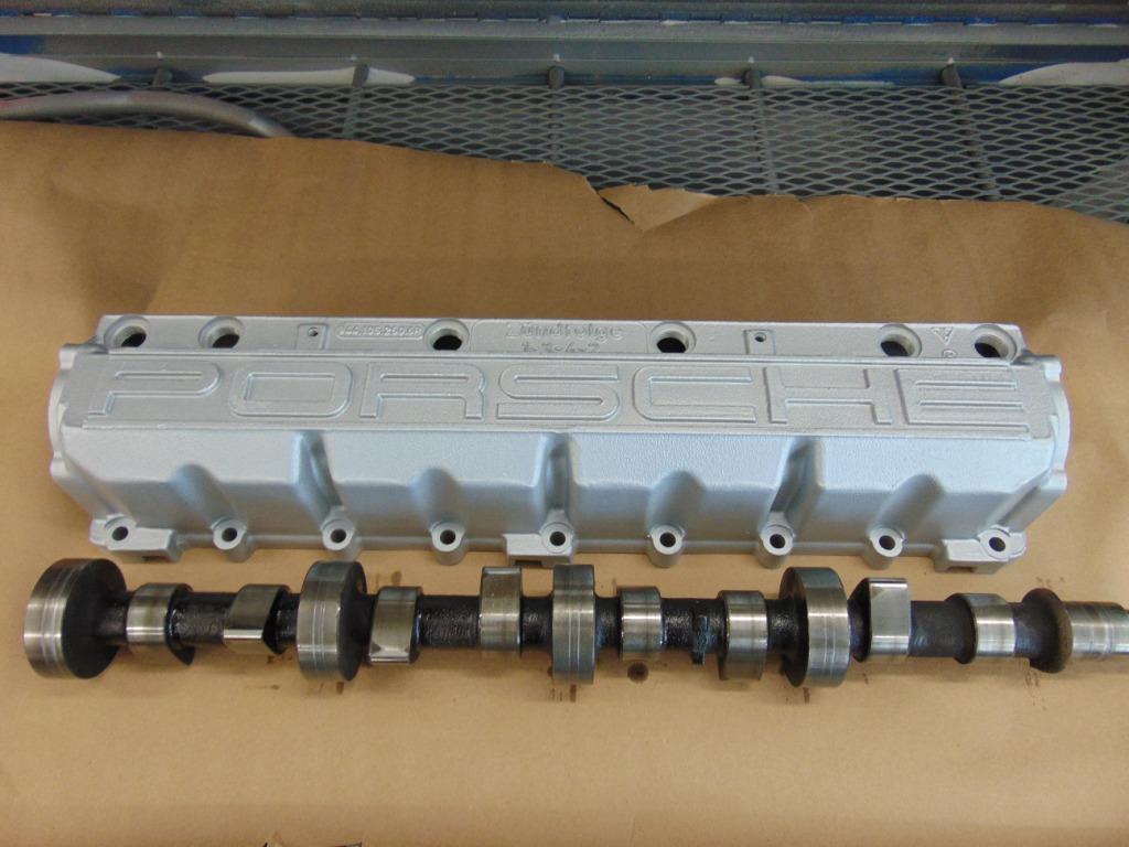
The cam, removed from the cam tower.
If you were smart when you lifted the cam tower off the head, you slipped a piece of cardboard or similar into the space as you lifted the tower, to capture the hydraulic cam followers from falling out. It is best to keep them in their as-found locations. That said, in previous times before I knew better, I’ve had them all fall out and get dis-organized. That particular engine survived with no ill effects so I don’t think it’s mission critical, just a nice thing to do if you can.
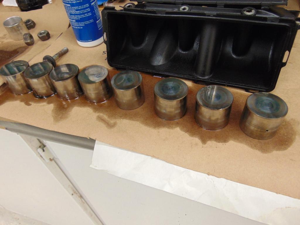
Hydraulic cam followers.
Removing the triple point (or cheesehead bolt) at the end of the cam is required to remove the cam gear and further disassemble the cam from the tower. You should purchase a good quality set of triple point sockets as you will use them a lot around a 944 engine.
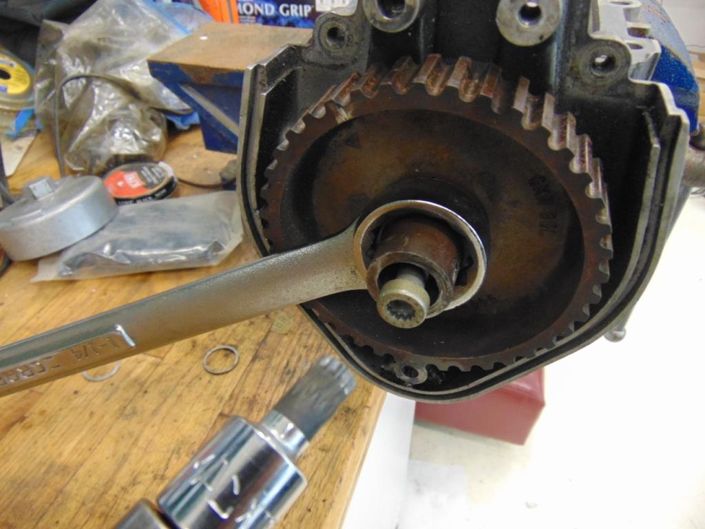
Hold the cam gear from turning with a wrench. This is the triple point bolt that needs to be removed. Having an impact wrench is a big plus!
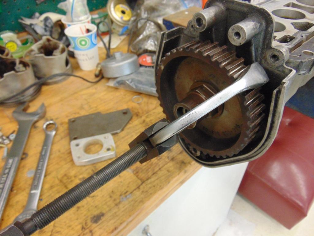
A specialty puller is a big help when removing the gear.
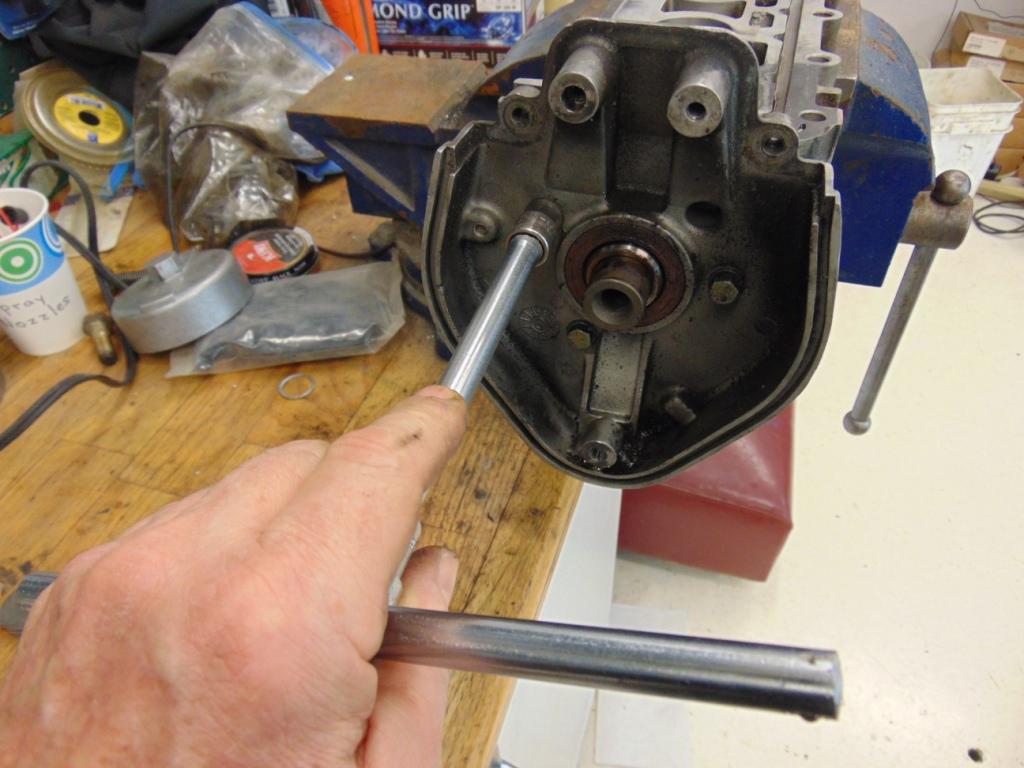
Remove 3 screws to release the end plate.
There is very little maintenance or rebuilding that I know off on the cam tower. You will certainly want to inspect the lobes on the cam for unusual wear. I can’t really tell you what unusual wear looks like but I suspect there is discussion on Rennlist that can be found using the Search feature. Of the few engines I’ve done, I’ve never seen anything that looked serious enough to investigate further.
The camshaft journals ride in bearing surfaces in the tower that are machined directly into the aluminum. There are no replaceable bearing shells.
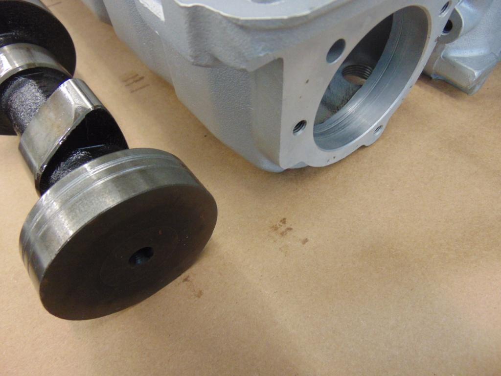
Cam journal engages an opening machined directly into the cam tower. There are no replaceable bearings.
As it is what I like to do, I removed my cam and did a thorough cleaning of the interior and exterior of the tower. Although I generally use glass beads for cleaning, if you do be very careful. Do not blast the interior surfaces where the cam bearings ride and/or the openings where the hydraulic lifters ride, as these are highly polished surfaces and need to stay that way. Also be aware that there is an oil feed to the cam tower from the block. If you look towards the rear of the cylinder head, there is a small (~1/4”) hole sticking straight up. It matches up to a mating hole on the cam tower. This is the oil feed from the main oil gallery in the block. See 944 Oiling System Explained for more info. You will want to make sure this passageway is clear by blowing solvent and compressed air through it. Ditto for the mating passages in the cam tower and the cam itself. Once everything is clean, apply some oil to the cam journals and re-insert the cam into the tower. You should replace all the gaskets at the rear and front of the cam tower that come with your gasket kit. The big cork gasket at the back end and the rubber o-ring at the front end are pretty obvious. A bit of sleeper is the small (~⅜”) round gaskets at the front cover for the oil feed hole.

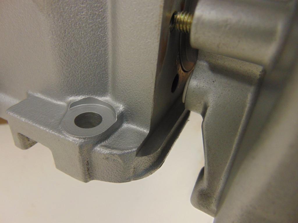
Make sure gasket opening lines up with the oil feed hole.
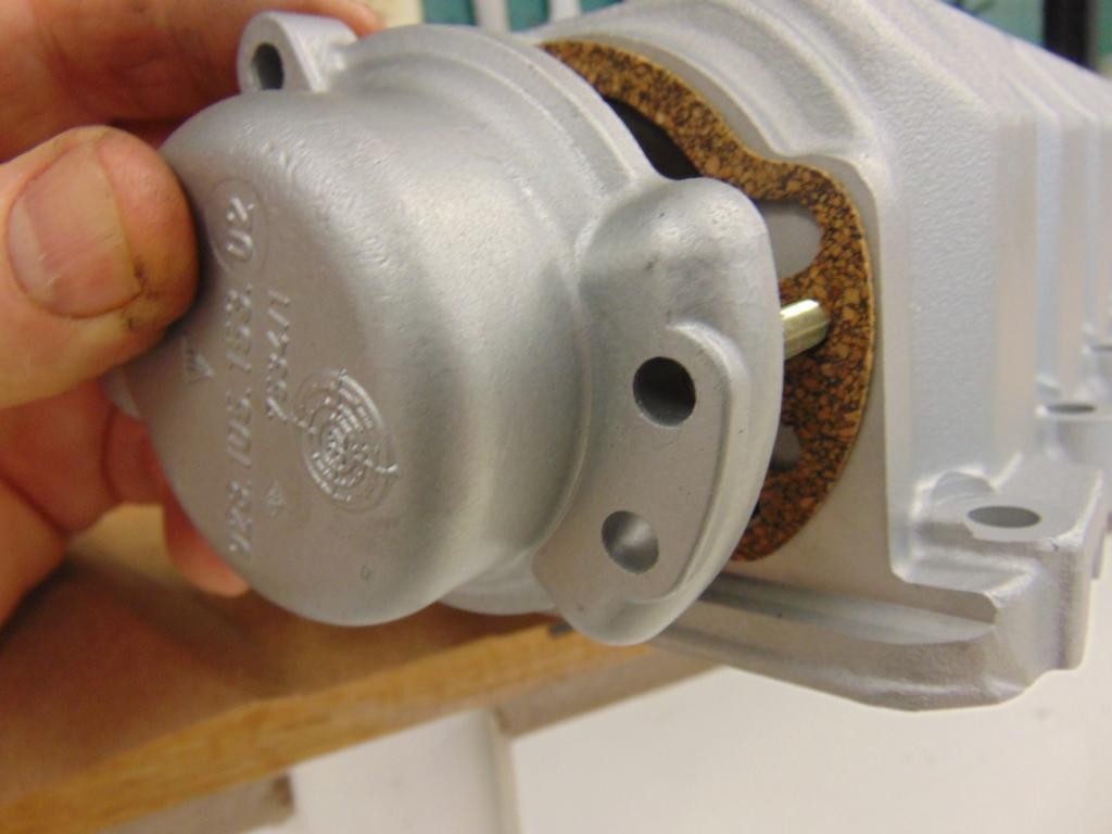
Gasket at firewall end of cam tower
This connection uses a large o-ring. There is also a small round gasket that allows oil to transfer. It is hard to photograph but it is the small white gasket just visible inserted into the right hand piece in the photo.
Assuming you removed the large triple point (also known as cheesehead) bolt at the front of the cam that holds on the cam belt drive gear, now is a good time to place the tower gently in a vice and torque this bolt to the value specified in the shop manual. You will apply counter torque with a suitable wrench applied to the wrench flats on the gear supplied for this purpose.
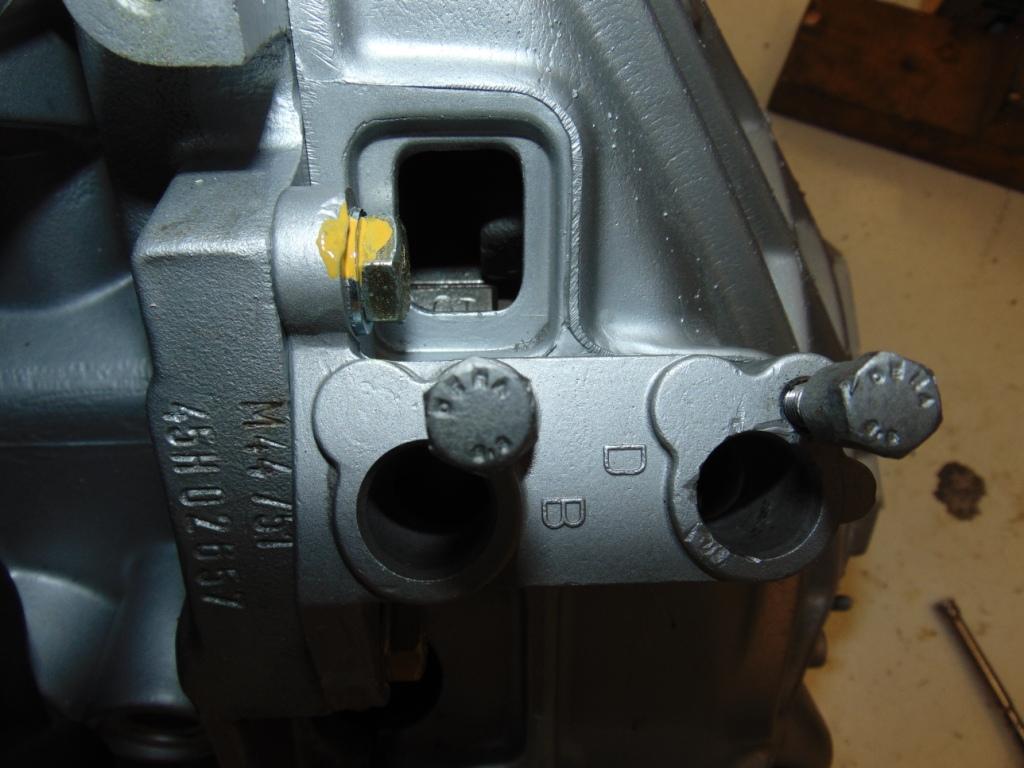
So the thing is, as you assemble and torque the fasteners for the cam tower, at least one intake and one exhaust valve will be opposite a cam lobe and will thus open. So you need to do a rough timing of the pistons and the cam. You need to get both in roughly the number 1 firing position. They don’t need to be exact, just close. The camshaft is pretty easy. The driven gear on the end of the camshaft has a mark that lines up with a fixed mark on the coverplate on the end of the cam tower. These marks are described in pretty good detail at Clarks Garage and/or the shop manual. You will need to be familiar with them as you install and tension your timing belt later. So set the cam at the number one position. As a double check, when you look at the camshaft at the #1 cylinder intake and exhaust positions, the two lobes will not be in position to open the valve.
If your engine is still on an engine stand, getting the #1 piston to the #1 firing position is a little tougher. That is because both the #1 and #3 pistons come up to top dead center at the same time. One will be on its firing stroke and one will be on its exhaust stroke. How do you tell? Well, you have to look at your flywheel. You hopefully know that the flywheel has a line etched at a precise location on its perimeter that you look at through a small window in the bellhousing when you set timing. The line also has OT stamped next to it.
TDC for #1 cylinder. A line and the stamp “OT”
The small window in the bellhousing is adjacent to the two crank sensors and is at roughly a 11 o’clock position when looking at the rear end of the crankshaft. You will want to clean this line up and maybe even mark it with high visibility paint so it will be easy to spot when you are checking timing. Anyway, find this mark. Then on the end of the crankshaft, there is a locating pin that engages a matching hole on the flywheel so the flywheel can only be installed at one location.
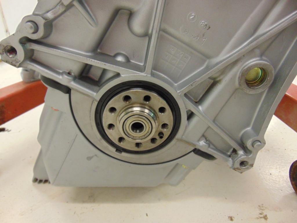
Locating pin on the end of the crankshaft. This allows the flywheel to be “clocked” to the correct position.
Visualizing the location of the hole on your flywheel for the locating pin and the OT mark, rotate the crankshaft so that, if the flywheel were installed, the OT mark on the flywheel would be visible in the opening of the bellhousing. As you rotate the crankshaft to do this, the #1 piston will be at or close to top dead center. Go ahead to set it reasonably close to top dead center and call it good. If you were to get it wrong i.e. the #1 piston on the exhaust stroke, the OT mark would be a full 180 degrees around to the other side so it should be pretty obvious. Of course, if you have the engine already situated with the flywheel installed and the bellhousing in position, this all becomes much simpler.
Now that you have the crankshaft and the cam both set to the #1 firing position, you are cleared to assemble the cam tower to the head. If you haven’t done so, lightly lubricate your cam followers with engine oil and insert them into the tower in the same positions they came from. The flat surface of the follower mates to the cam lobes. The hollow opening side will sit over the valve stems. You will of course want to install a new paper gasket from your gasket kit. It is positioned with 2 pins that will ultimately engage with and position the cam tower. Use the same cardboard trick to get the tower into rough position without the lifters falling out.
The cam tower is held in place with internal hex head screws. I live in fear every time that I have to pull a cam tower that one off these internal hex screws will fail at the hex head during disassembly. As such, I like to replace them with new fasteners. You will also need to invest is a set of good quality ⅜” drive allen keys, of sufficient length to reach down into the internals of the cam tower. Coming out and going back in, I like to put a dab of gooey chassis grease on the end of the hex to make the screw stick and not fall out at a critical time. If the screws do fall off, they can generally be retrieved with a magnet but it is certainly a PIA when this happens.

There is an allen head screw at the end of this tool. A dab of chassis grease helps hold them on to the tool.
You will want to get all the screws engaged and started. Don’t forget to attach the hardpipe for the waterline to the heater. As you snug up the screws, the tower will be held off of its final position by the 2 valves that are being held open by cam lobes. As such, you will want to gradually tighten the screws a few turns at a time, working in a pattern, until the tower is in full contact with the gasket. Then apply final torque to the screws in accordance with the requirements in the shop manual. At this point, you can also install the aluminum plugs with their washers into the access holes on the top of the cam tower.
From now on until the timing belt is installed, resist the temptation to rotate the cam shaft or the crankshaft. I’m not sure you could bend a valve with just hand pressure but there’s no need to find out! And that’s it for the cam tower. Next time we’ll swing back around to a bunch of ancillary components that I haven’t discussed so far, like the oil pan, oil pump, water pump, and clutch.
Special tools you will need:
Torque wrench
Allen wrenches, long, socket drive, ball end preferred
Triple point sockets
Gear puller

Discussion
Comments are closed.