The torsion bars on the Etype have a certain bad reputation for being difficult to deal with. My experience would tend to support that experience, although I think I learned a few things in the process that will make it easier the next time and hopefully for others.
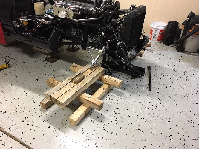
I had recently completed installation of the engine on my on-going restoration of my 63 Etype and I was ready to install the torsion bars. Generally speaking, the front suspension of the Etype uses a straight round bar, loaded with a twisting force (torsion), to provide the “spring” resistance required to support the weight of the car at the front wheels. Conversely, the rear suspension uses four standard coil springs. The “ride height” of the rear suspension is not designed to be easily adjustable. But the ride height at the front of the car can be adjusted by the torsion bar installation. As a result, you may have found this article because you are not happy with the ride height at the front of your Etype and want to correct the situation. Hopefully this article will help you do so.

The ride height obtained from the installation of the torsion bars is technically adjustable over a wide range. There are several factors here. The torsion bar is just a straight steel rod. If you hold one end firmly fixed and apply a “moment” force (English units are foot-pounds), the rod will consistantly rotate or twist to a known value that is porportional to the moment applied. If for example the car weighs 3000 pounds and there is perfect distribution of 750 pounds at each wheel and if the wheel is supported by a suspension arm that is 12″ long, then the applied moment will be 750 pounds x 12 inches / 12 inches per foot =750 foot-pounds. The rotation of the torsion bar is a function of its diameter to the 4th power, it’s length, and a material constant based on the type of steel used. So in the design phase, you can select a torsion bar length and diameter to give a spring rate at the wheel that is best for performance and comfort. But for most of us, we just want the front of the car to be at the same ride height as the rear, or maybe with a tad bit of downward rake. So we may experiment with different torsion bar installations to get the profile we want when viewing the car from the side. That is where installing and adjusting the torsion bars comes into play.

I found that installing the torsion bars is not that difficult if you know some tricks. Adjusting the torsion bars is just a subset of installing them. To that end, I have prepared a video demonstrating the technique that I used to install my torsion bars. Keywords are torsion bar, splines, A-arm, torsion bar rear bracket, reaction plate, and setting link. All of these are discussed in the video. It is broken into 2 parts due to Youtube limits on video lengths.
Installation Notes for Torsion Bars Part 1
Installation Notes for Torsion Bars Part 2
Now that you have hopefully watched the videos you should be familiar with the approach I recommend. Just to summarize, here are some key points that I would stress:
- The lower A-arm must be fully released from the other suspension parts. This allows the A-arm to be able to fully “droop”. Depending on your situation, you can release the upper ball joint or the lower ball joint. Also the shock absorber/damper must be removed. More on that later.
- Confirm that the lower A-arm is installed in the correct orientation, with the machined surface where the torsion bar splines engage on the forward side of the arm. The causes the torsion bar to emerge at a 1 degree 30 minute angle towards the middle of the car.
- All key components should be checked for ease of insertion. This includes the front and rear splines, the fitment of the reaction plate into the tub, the fitment of the rear bracket “boss” into the (hopefully ) aligned holes in the tub and reaction plate, and the alignment of the two holes for the 3/8″ fixing bolts.
- Insertion of the front splines is easiest with the A-arm in a roughly horizontal position.
- Insertion of the front splines may be aided by releasing the rear bracket of the A-arm.
As discussed in the video, following these tips will help you as you determine the correct static position for your torsion bar with no load placed on the suspension. When you get the car fully loaded and have got the suspension fully settled, hopefully you will be happy with your ride height. So let’s talk about a few other things.

Vernier action of the torsion bar splines – This seems to throw some people for a loop. Let me take a shot at explaining the situation. There are 24 splines on the front of the torsion bar and 25 splines at the rear. This situation is commonly referred to as applying a “vernier” effect. Doing some simple math, 360 degrees / 24 splines = 15 degrees per spline. 360 degrees / 25 splines = 14.4 degrees per spline. If you just rotate the front (or rear) of the torsion bar 1 spline, you are going to get a big jump in the rotational position of the A-arm. The trick is to rotate one end 1 spline (say) clockwise and the other end 1 spline counter clockwise. The net rotation is 15 – 14.4 = 0.6 degrees. Obviously this is a much finer adjust. So in the video I talk about rotating the front of the bar say CW one spline. What I say in the video is to put the rear bracket into the best position to align the holes. But another way of saying this is that the rear bracket is moved one spline CCW, yielding a very small change from your previous “guess” for torsion bar position. That is how the vernier concept works for the torsion bars. In the video I stress picking a direction (CW or CCW) for rotating the front splines, one spline at a time per attempt. Since during the process you pull the rear bracket totally off the splines onto the round part of the bar, you are really losing track of which way you rotated it but trust me, if you pick the best position, after rotating the front by 1 spline, at the rear you are by default going in the opposite direction of how you rotated the front.
The main reason to I discuss the vernier action is to help you understand why in the video, we adjust the fitment of the splines at both ends of the torsion bar. This lets you make the fine adjustments you need to get the holes in the rear bracket to line up with the ones in the reaction plate, for a target setting length.
How can I calculate how much to rotate the torsion bars to raise or lower my front ride height? Some folks want to calculate how many splines to rotate. I prefer calculate a new setting length and rotate my torsion bars until that length is obtained. This involves some basic math.
1) Let’s say your existing ride height is too high. You’ve decided you want to lower it by W inches.
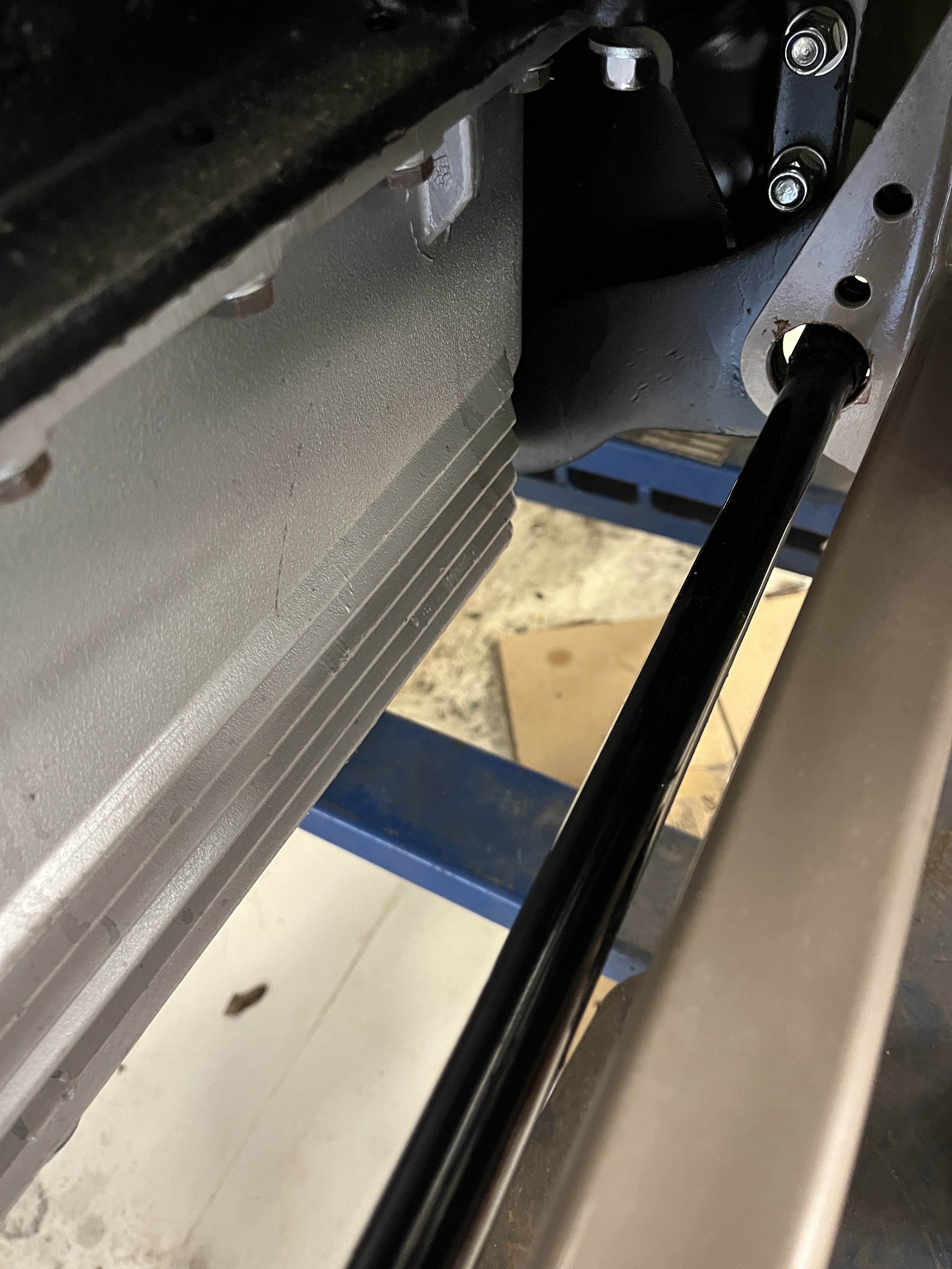
2) With the car on a level surface and with a “normal” fuel load, measure the length between the lower and upper shock mount bolts. The center to center dimension is technically what you want, to about 1/8″ accuracy. To lower the car, you are going to need to reduce this dimension by 0.75xW inches. (The 0.75 factor is discussed below)
3) Now you will need to dis-assemble the front suspension (also discussed below) until the lower A-arm is in its relaxed configuration. You will once again measure the length between the lower and upper shock mount bolts. Since we said in 2) that we want to reduce this length, your new target setting length is 0.75xW of this dimension.
4) Make a new setting link with your new target center to center hole spacing.
5) Use this new setting link and the process in my video to find the torsion bar spline position that gets you where you need to be.
There is no need to count splines or anything like that. Trust me, 10 minutes of trial and error will yield a solution! If your car is too low, just add 0.75xW instead of subtracting.
Tom Rutherford of Jag-Lovers suggests that math is much easier with an example problem.
You are raising your car 1.5″. So you have to increase your setting length. A longer setting length makes the car higher.
17.75+0.75*1.5=18.875 inches
You can use metric or inches, whatever is easier. Just stay consistent.
1.5 inches is a big change. Just be sure that’s what you want. Maybe on a flat surface, use a floor jack with a wood block under the rad support. Then you can try different heights and take careful measurements. Measure twice, adjust once.
And remeasure your current setting length when you get to that stage in the disassembly. (just before you pull out the torsion bars.) “But I measured it when I put it in” you say. Measure it again to account for settling which we have read about.
You may ask, why is that 0.75 in there? This represents the ratio factor between the point where the shock absorber connects to the A-arm and the outer ball joint. In other terms, on my car I measure 8.25″ from the bolt for the shock absorber and the rotation point i.e. the fulcrum shaft. The distance from the lower ball joint to the fulcrum shaft is 11″. To make the vertical position of the lower ball joint change by 1″, you only need to move the shock mount by 8.25″/11″ or 0.75. This is sometimes called a “motion ratio”. The ride height is measured at the lower ball joint, not at the shock mount, which is why this factor needs to be applied.
How do I disassemble my suspension?- As you can see in my video, I was in the process of assembling the suspension as part of a restoration. If in the more likely case that you are working from a running driving car, the process is described in the factory workshop manual (see image at the end of this article). I have included an image of the pertinent pages at the end of this article. My only advice is to go ahead and break lose the lower ball joint and tie the stub axle carrier out of the way. And replace both the upper and lower ball joints while you are in there.
What if I install Uprated Torsion bars? – Uprated usually means stiffer bars, which always means a larger diameter than stock. Unfortunately, since the stiffness of the round torsion bar is a function of the 4th power of its diameter, this situation is not linear. I will give you an equation below that will get you close. This assumes you like the ride height you have but just want to put in bigger diameter bars. BTW, a larger diameter torsion bar is not a fix for a low ride height. All it will do in make your car stiffer over bumps and reduce body roll during cornering.
- Before you pull things apart and with the car on its wheels, measure the length of the shock absorber. We’ll call this A.
- Measure the outside diameter (OD) of your old torsion bars. We’ll call this B.
- Measure the outside diameter of your new torsion bars. We’ll call this C.
- As discussed below, remove components to allow the lower A-arm to go to its relaxed position . Measure the position between the two shock mounting holes, with the A-arm in its relaxed position. We’ll call this D.
- Your target setting length is: New setting length = [(D – A) x (B^4 / C^4)] + A
- Generally, the new setting length is shorter because your new stiffer torsion bar will twist less under the static load of the car.
Are torsion bars handed? – Based on my knowledge of material science and machine design, I think the original torsion bars were identical right and left but I admit they have 2 part numbers in the SPC. There is a theory that once you put them in service, they become handed and should not be swapped side to side. For new bars, check and see if they have a R or a L stamped on the ends. Install accordingly.
Do torsion bars sag or wear out? – There are enough anecdotal complaints of this on the forums that I guess it can happen. New torsion bars are not that expensive in the great scheme of Etype costs. If in doubt, I would replace them.
What was the diameter of an OEM torsion bar? – Currently, most vendors sell a larger diameter uprated torsion bar. SNG for instance shows one at 0.860″. Months ago, I did some research and pestered my contacts at SNG to sell me an OEM diameter bar. The SNG part number is SBS9014. The one I received and installed measures 0.775″, with paint. The setting length of 17 13/16″ given in the workshop manual (see image at the end of this article) in my mind only works for that diameter bar. Yes, I know the ride will be “soft” but that is how the car was designed. As an aside, I am mounting 6.40 x 15″ bias ply tires, just for the full experience!
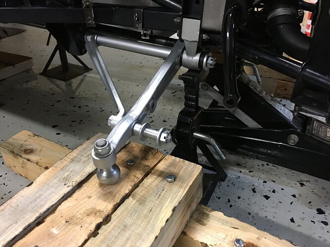
How can I check my work without fully re-assembling the suspension? I poised this question to Jag-Lovers and it resulted in a spirited discussion. My answer is yes, with a few caveats.
Mark posted the picture below, which is a concept that I like. In the picture, he has used an old lower ball joint, assembled into the tapered hole for the lower ball joint. The A-arm swings through an arc as it is loaded up and Mark’s configuration allows for this movement. His car is of course missing some weight items but I don’t see why this wouldn’t work assuming the major weight items, mainly the bonnet, are in place. You will have to do a little work to convert the measurements for ride height in the workshop manual to this setup. I like it because if the load slips off the balls, the jack stands under the fulcrum shafts will catch the car. A suggestion, if you own a digital level. The car must be level side to side. Before you begin, measure the slope (in degrees) of the A-arm and write this number down. When you come back with the arrangment shown, measure the slope again. You can use the Small Angle Formula to calculate how much the ride height has changed. See the article here.
I hope this has helped. I will find out in a few months time when I get the car down on all 4 wheels, fully loaded, whether I have to tackle this job again.
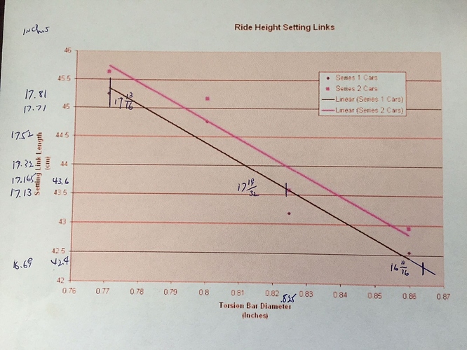
Here is a chart that showed up on Jag-Lovers that attempts to use math to give you a modified setting link length for non-standard diameter torions bars. I cannot attribute to anyone but, to whoever did it, Thanks!
Workshop manual file for Front Suspension-

Discussion
Comments are closed.