After getting the engine installed, I have been busy with various smaller tasks in the engine compartment. As usual, some tasks went well and some made themselves difficult. I’m going to post a bunch of photos but just to start things off, here is a video that I did that may be of general interest in identifying some items that you may have heard of and always wondered where they resided.
Hopefully that was helpful. Now on to my more typical text/photo essay. In no particular order.
Generator– Yes, this old girl has a generator, not an alternator. Because my goal is to make this car the same as it came from the factory, I ruled out an alternator or even an alternator disguised to look like a generator (these don’t look quite the same and when you get to the voltage regulator things get worse). I found an old school electrical repair shop locally. They tested the generator and pronounced it good. I did my standard detailing job. Black enamel paint on the body. End caps lightly bead blasted to refresh the cast aluminum.
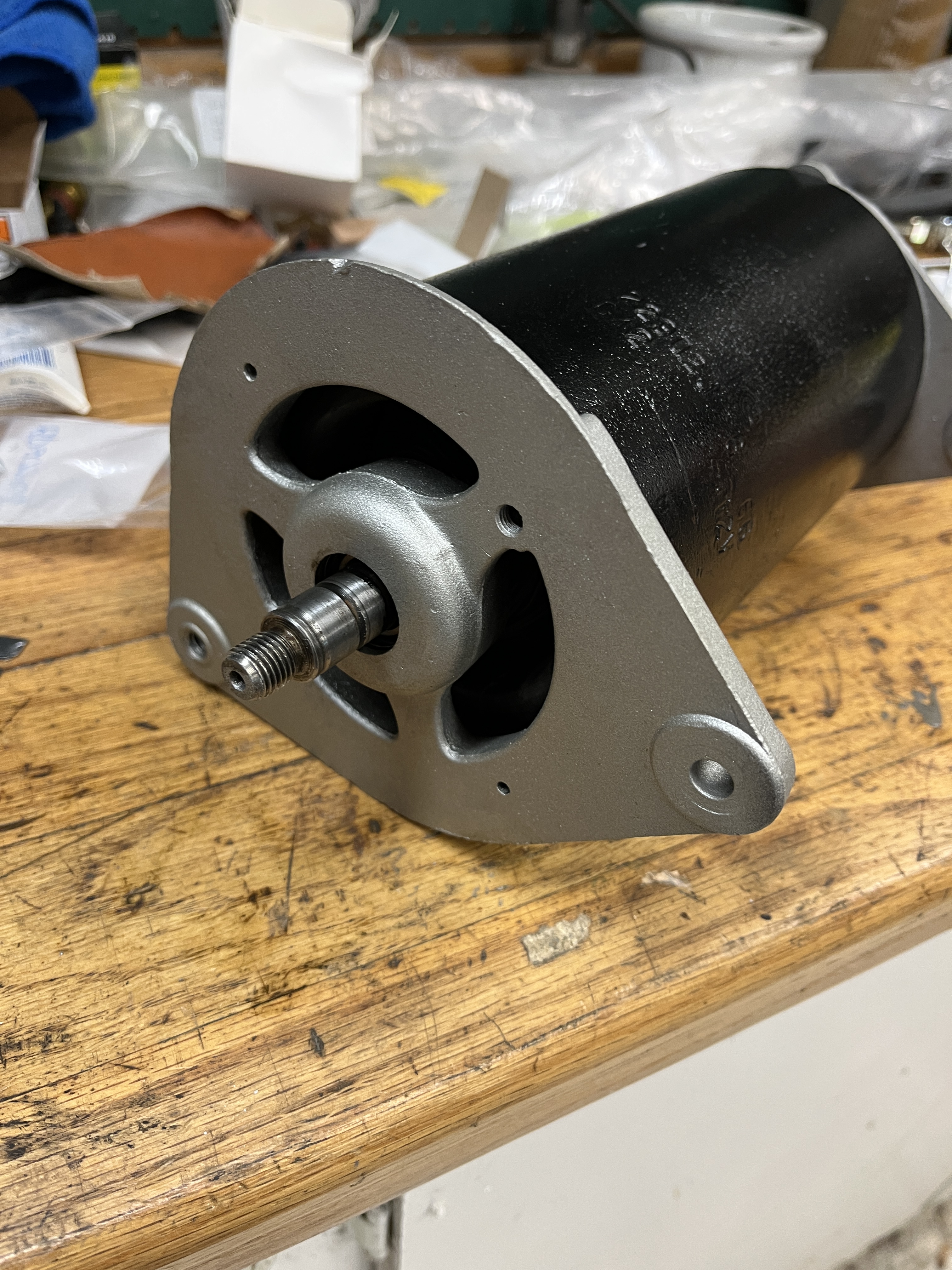

Here is shot of the generator installed. A couple of comments. The fellow who answers the phone at East Coast Jaguar (302-475-7200) was very helpful. He sourced the missing “fan” mounted between the pulley and the generator body, as well as an obscure spacer that holds the fan in the correct position. We also discussed the bracket that holds the generator in a fixed position at the top. It turns out I had the correct bracket. I just didn’t know what it looked like. There is a thick “distance washer” between the bracket the front cover of the engine, that puts everything in the correct alignment. The idler pulley, not visible on the far side of the picture, provides the correct belt tension.

Voltage Regulator– To make the generator work, you need a voltage regulator. Generators are dumb beasts. The harder you work them, the more they produce. This quest for higher and higher output voltage can be destructive to components. Thus the need for a voltage regulator. It does what it’s name implies. In a rather clunky steampunk way. When the voltage gets too high, a magnetically driven contact opens and shuts down the generator. The voltage drops. The contact opens. And back and forth, maintaining an output that is roughly 12 volts, plus or minus. The battery helps smooth all this out. Anyway, my box of parts included a voltage regulator that had the correct part numbers. When I opened it up, it looked pristine inside. Hopefully, it will work as advertised.


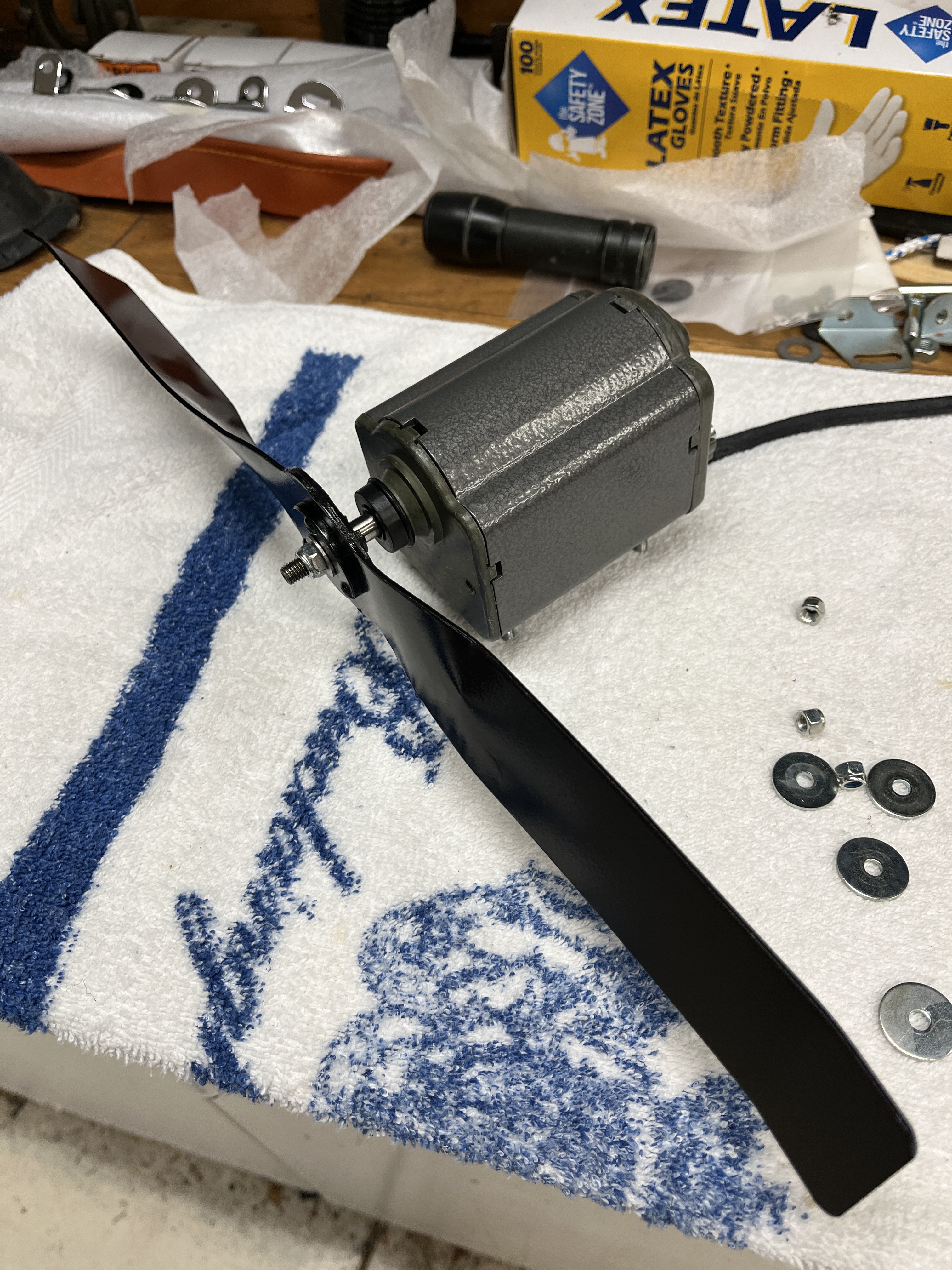
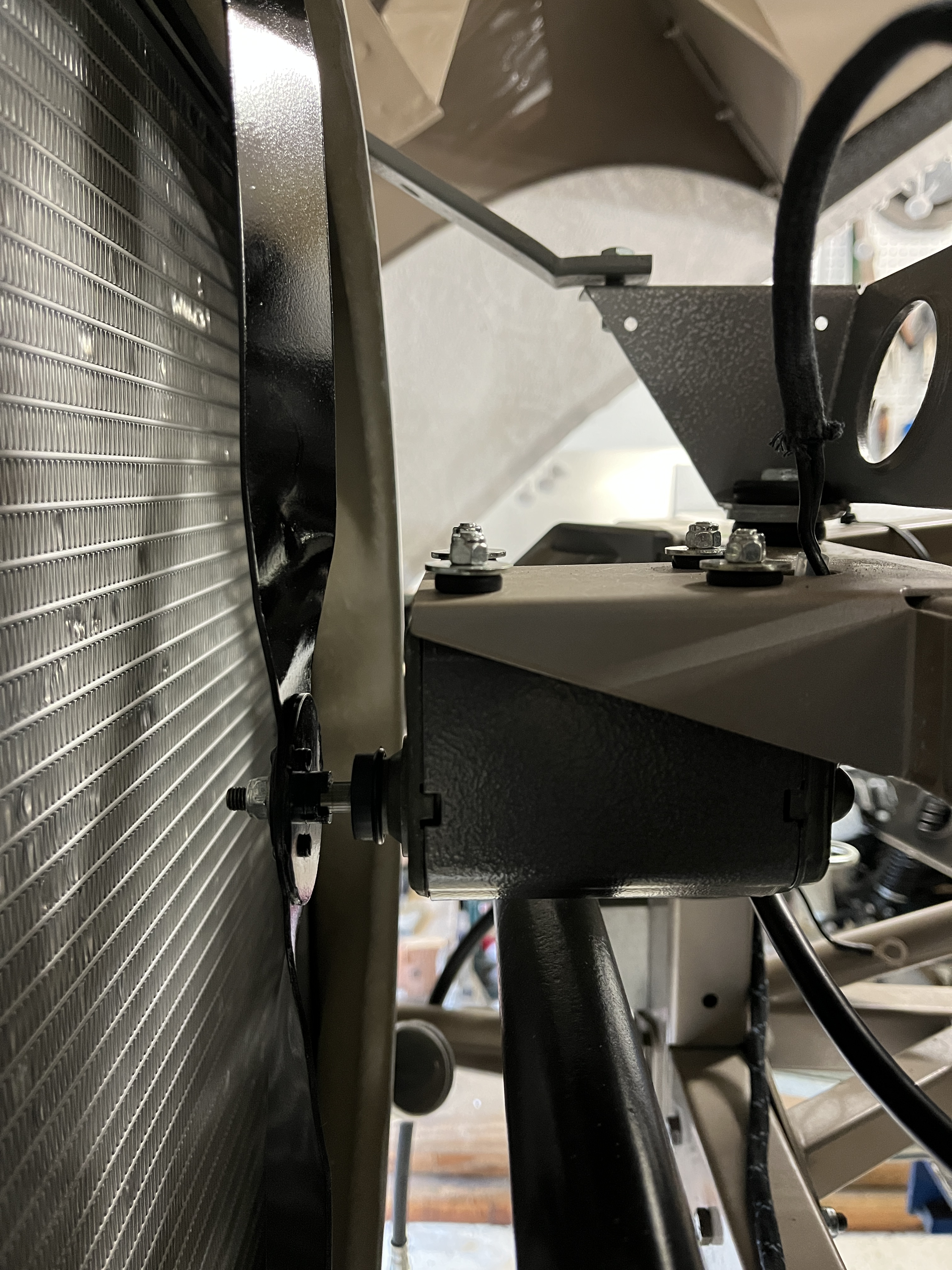
Radiator Cooling Fan – Such a pathetic device! Again, for the sake of orginality, I am going back with the original fan but seriously, what were they thinking? The fan motor that came in my box of parts did not work and all my fettling did not bring it back to life. SNG sells a genuine Lucas replacement, that externally looks identical. I purchased it and painted the fan blade with black enamel. It all mounts on a little pedestal cantilevered off the front of the picture frame.
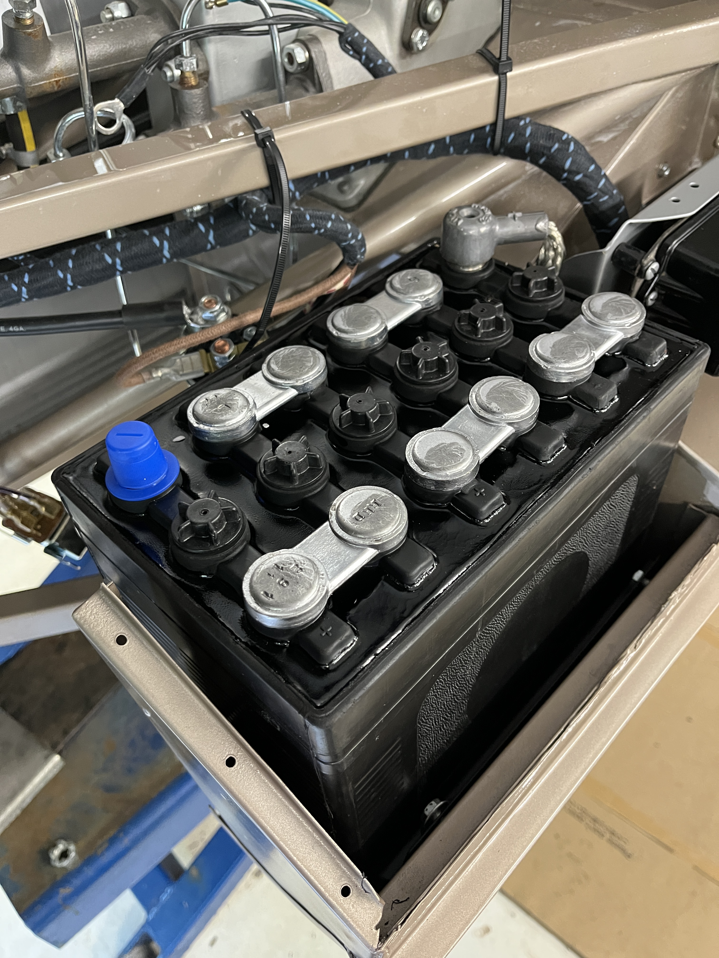
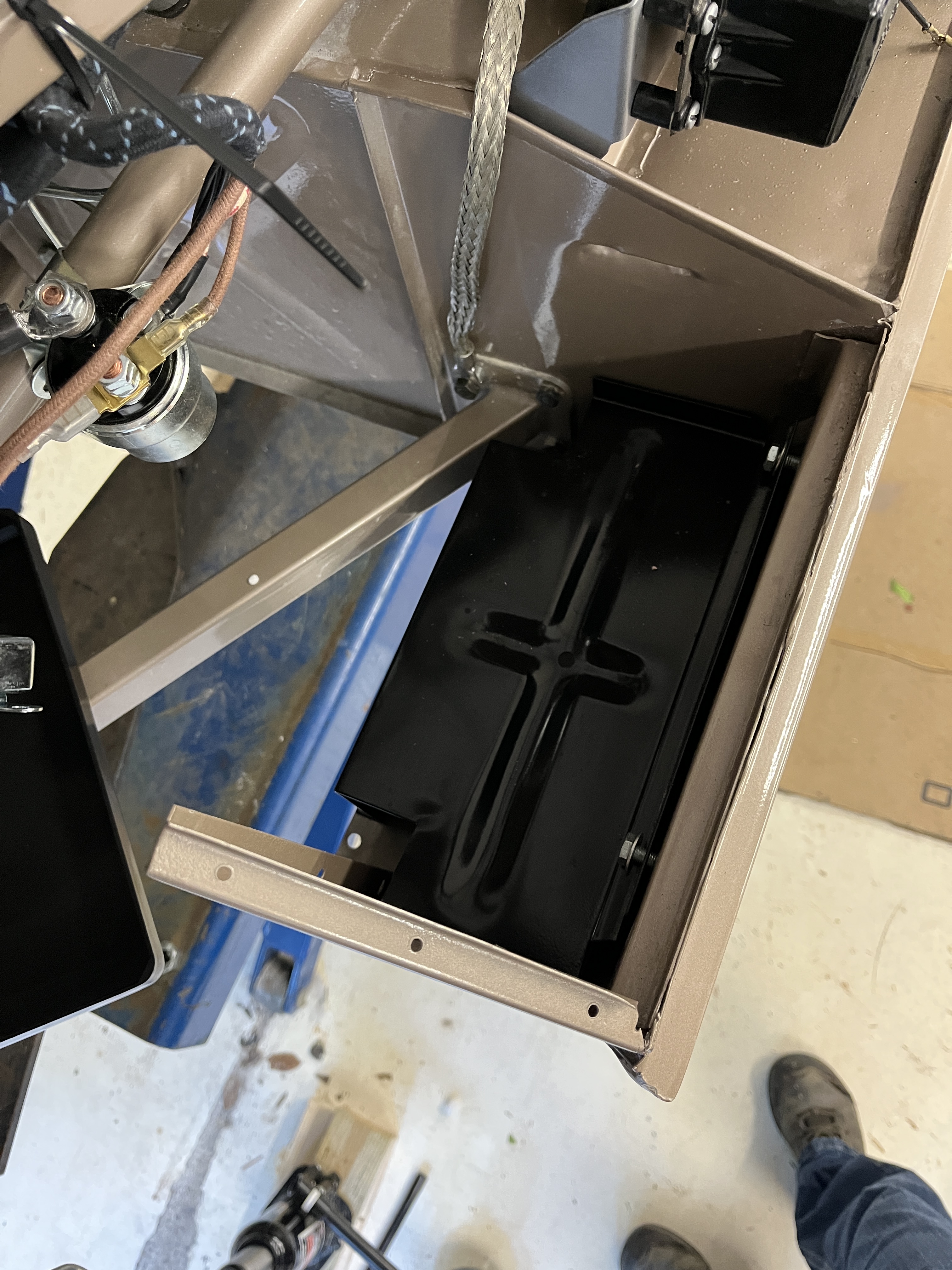
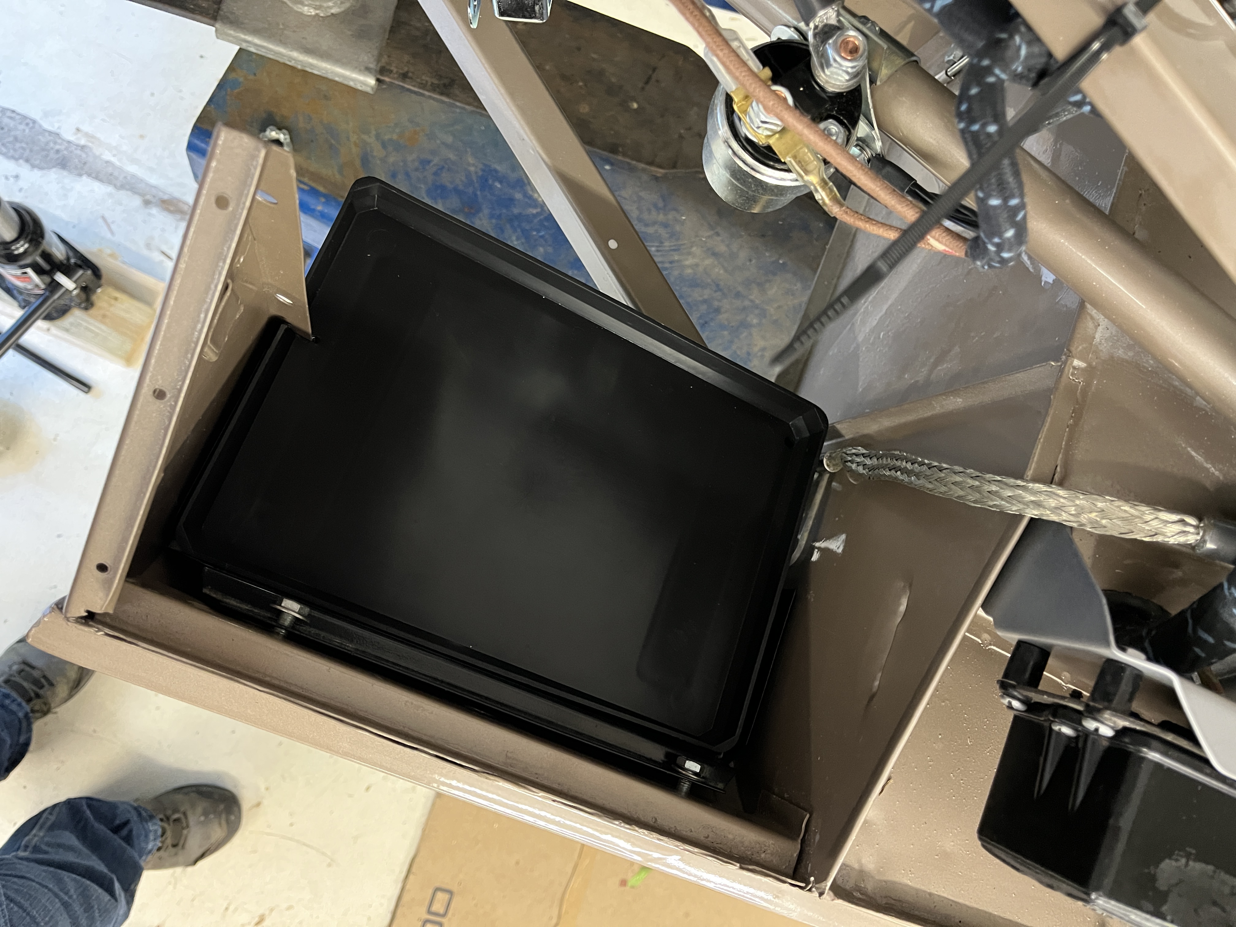
Battery– Speaking of batteries, I purchased an old school look battery from SNG. In hindsight 55 years later, the exposed metal terminals between the cells does not seem to be a good idea but that is how they did it back then. SNG ships this one dry and you add the electrolyte yourself. The electrolyte is available locally. At this point I am just test fitting it, dry.
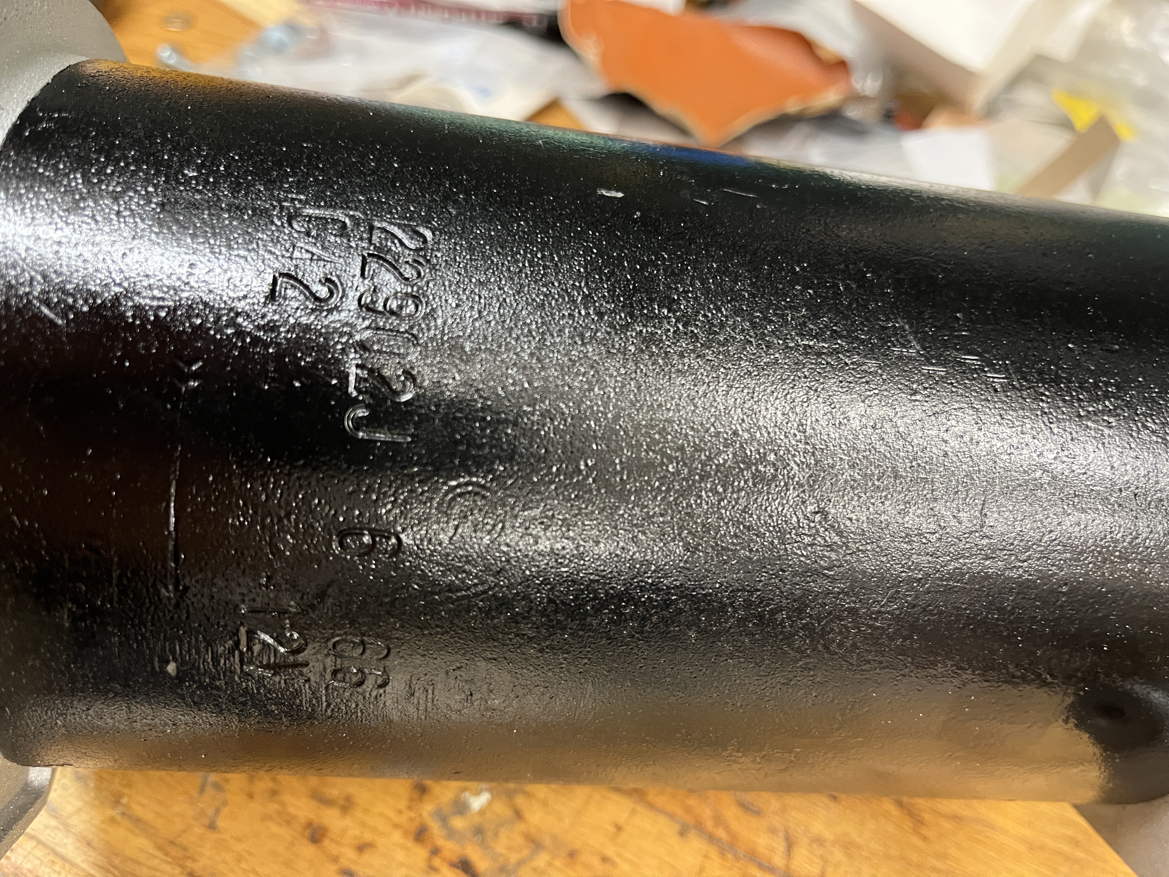
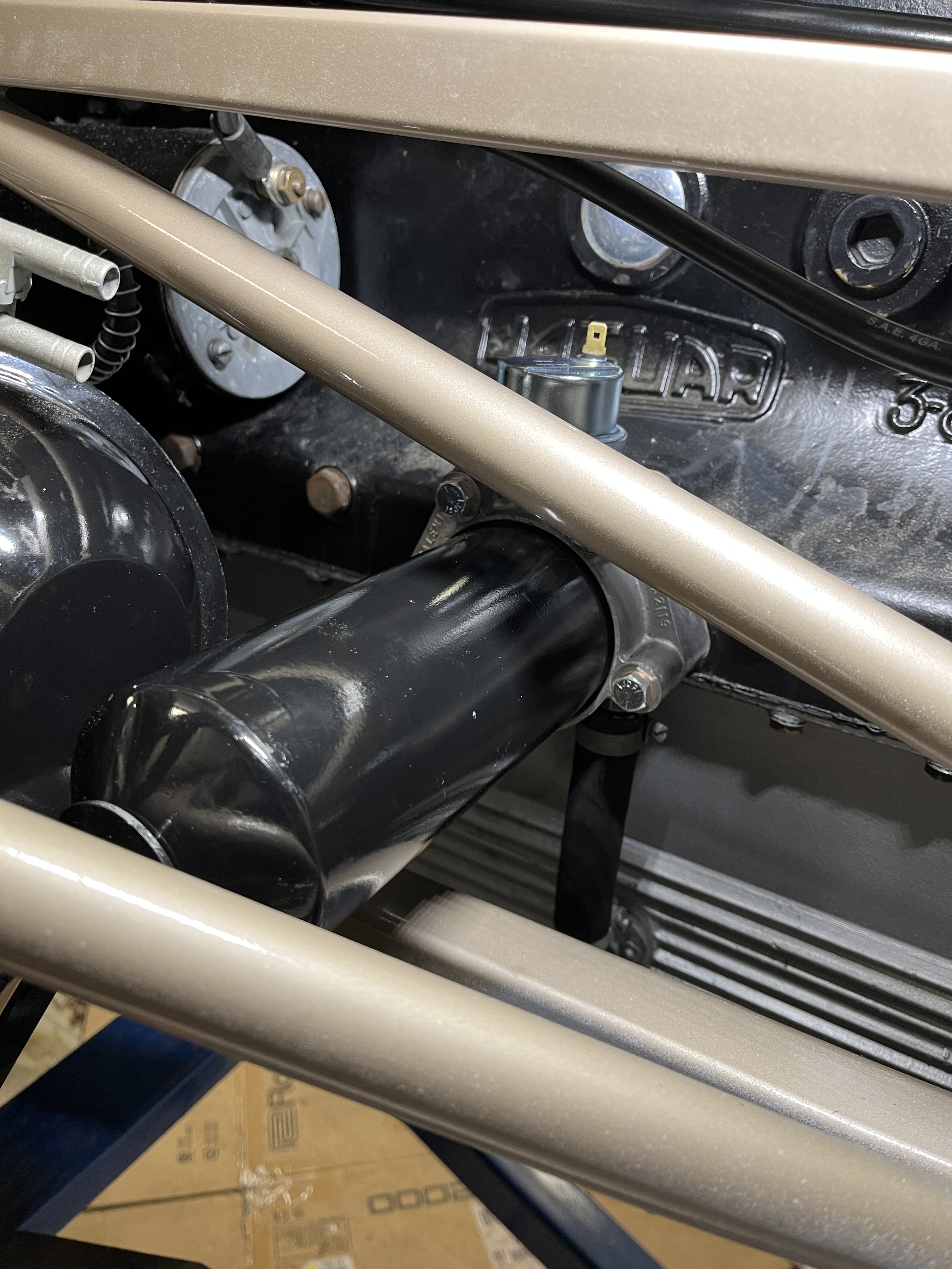
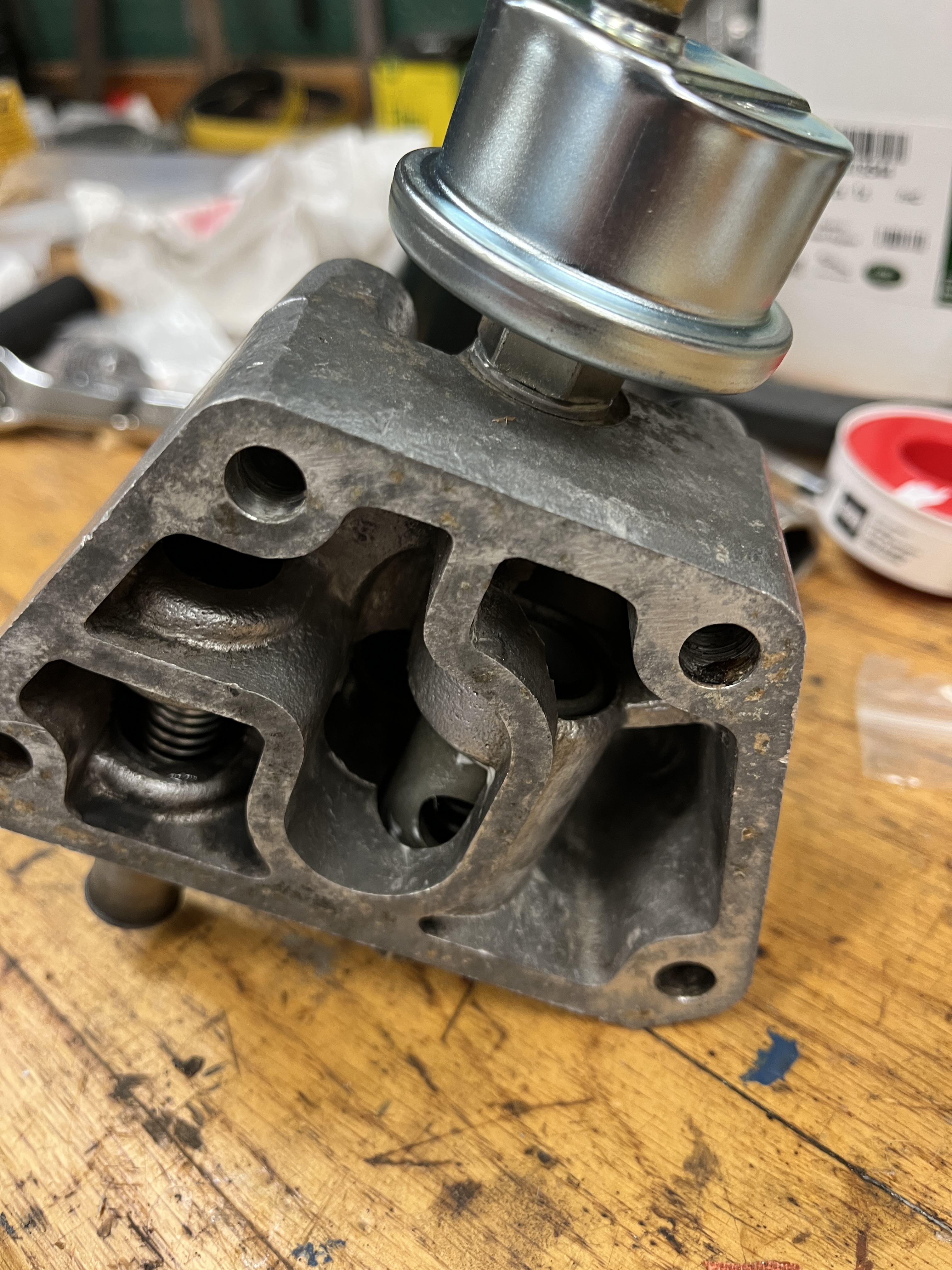
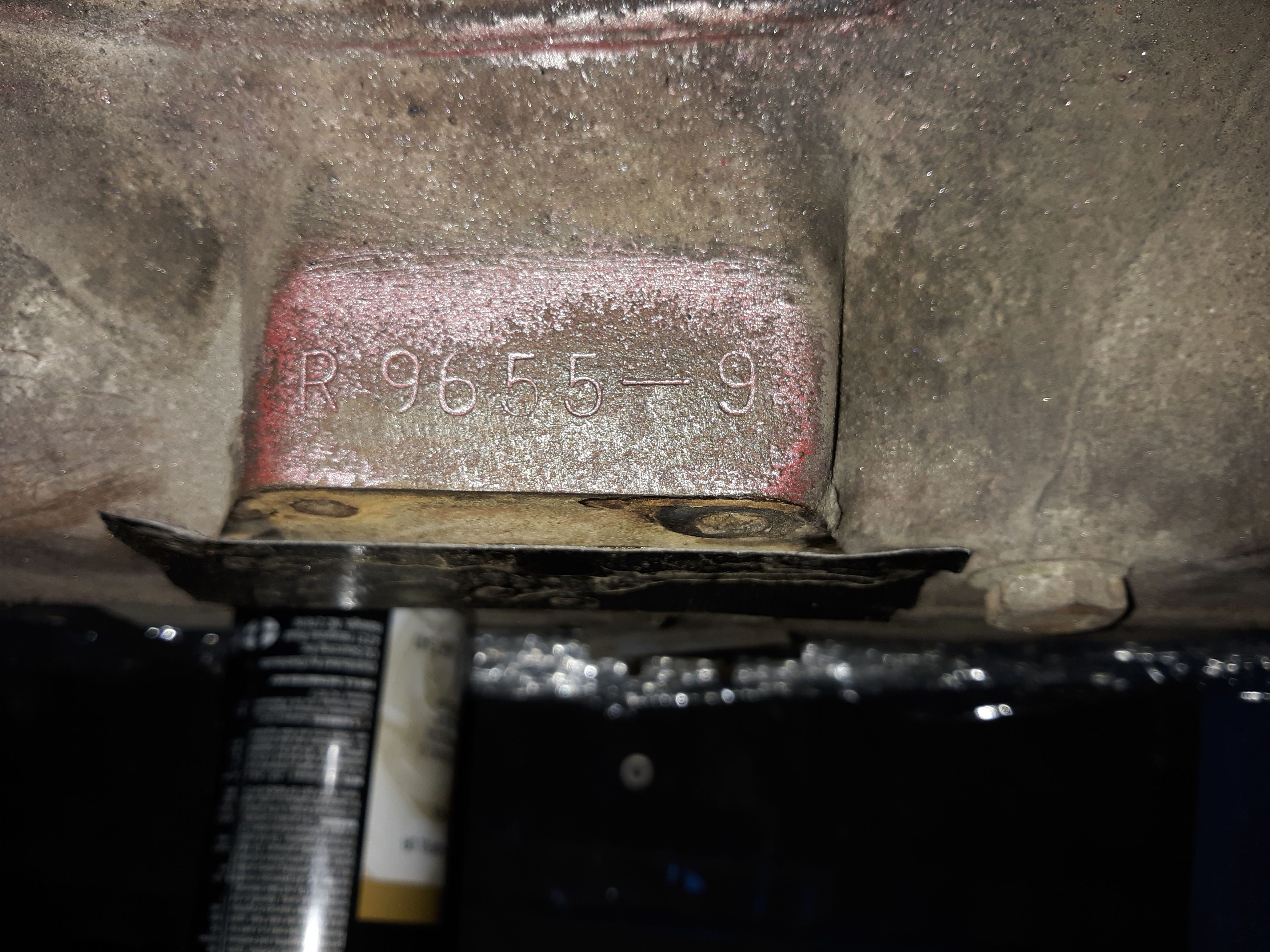
Oil Filter– the oil filter is a cannister type, with a paper filter inside. It is a little messy to replace but it is authentic. The filter canister mounts to an casting that bolts to the side of the block. It is slightly complex internally, as it supplies oil to and from the filter, it has a bypass for a clogged filter, and it provides an overpressure relief path back to the sump i.e. an oil pressure relief valve. I replaced the spring on the valve and all the basic gaskets. More black enamel paint was applied to the cannister. The sending unit for the oil pressure gauge is also plumbed in here. BTW, the “engine number” is stamped into the block just above the oil filter.

Torsion bars– See a separate article here.
Front Suspension– Last but not least I was able to complete the front suspension.

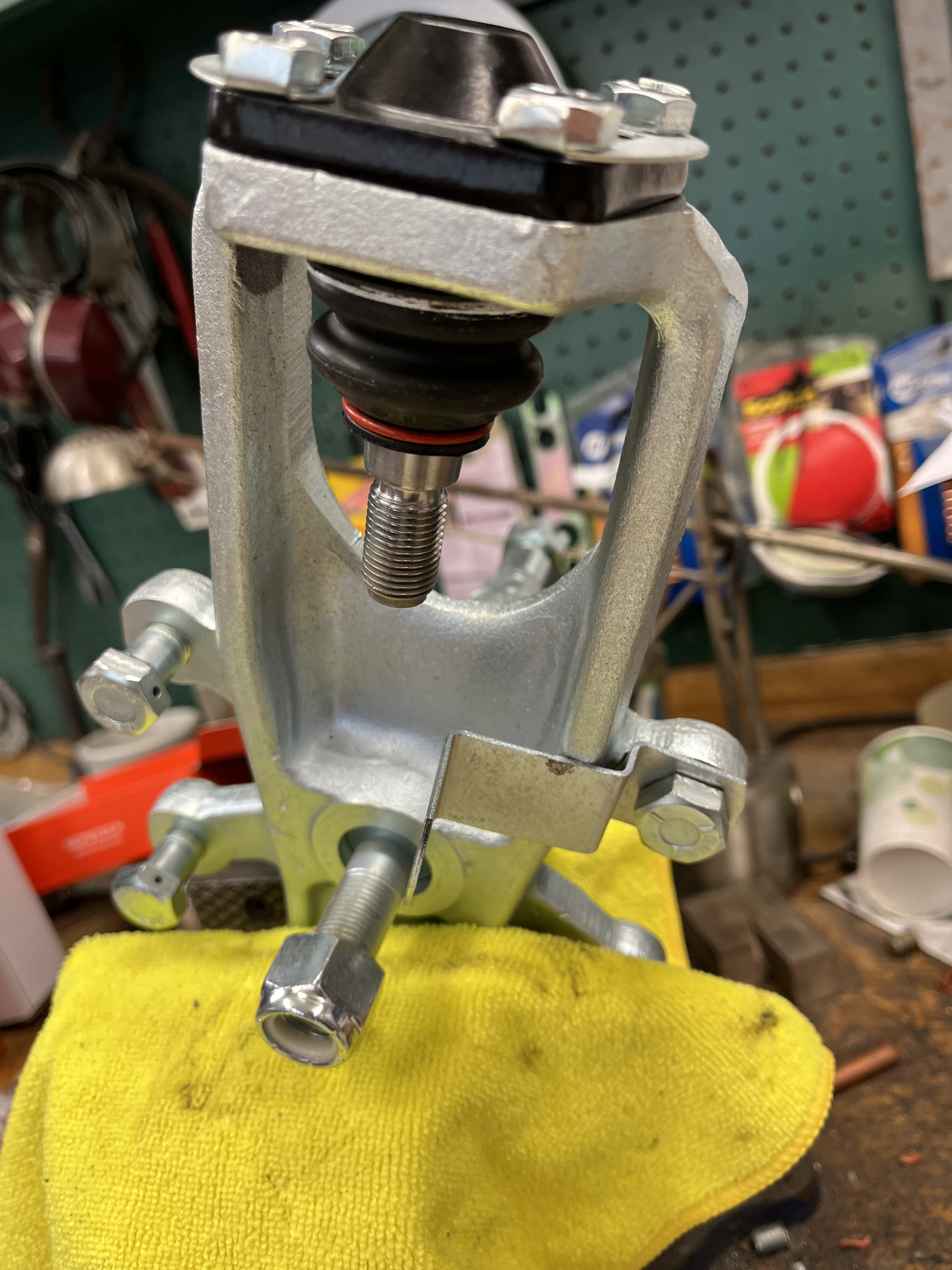
This is a shot you won’t often see. Shown is the “stub axle” where I am testing fitting the inner and outer hub bearings. They are a slip fit on the stub axle. The stub axle is supported by the “stub axle carrier”. It has ball joints on its lower and upper ends. These attach the the lower and upper A-arms. The carrier also provides a mounting point for the brake caliper. In this photo, things are just loosely fit as I determine what parts and hardware that I am missing.
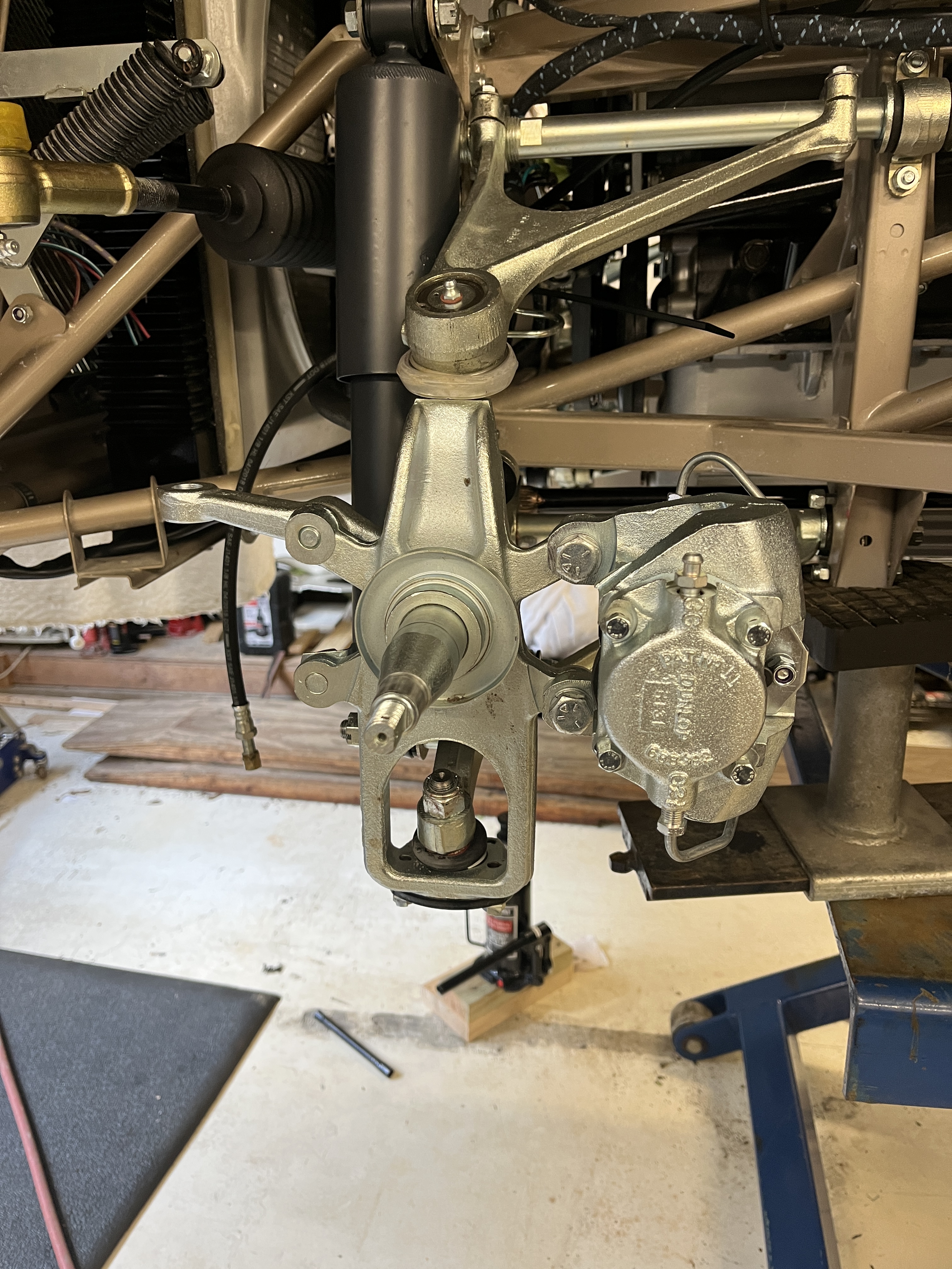
This picture shows the upper ball joint, the upper A-arm, the upper fulcrum rod, and the damper/shock. The dampers are from the new line of products developed by SNG in coordination with Girling. The Dunlop piston and cylinder assemblies are period correct ones that I paid a small fortune for off Ebay. They were then stripped and sent out for zinc plating. Finally, White Post sleeved them and installed new seals. If you don’t need that level of originality, buy the reproduction ones from SNG, which will look the same but will not be stamped Dunlop. Strangely, my box of parts came with similar pistons that were stamped with Dunlop and Sumitomo. Some research indicated that in the early days of disc brake technology, Sumitomo licensed the technology from Dunlop and it was used on certain Japanese cars. And I still have them, if someone needs them. How they got into my boxes I’ll never know. And yes, in this photo my brake calipers are mounted on the wrong side of the carrier.
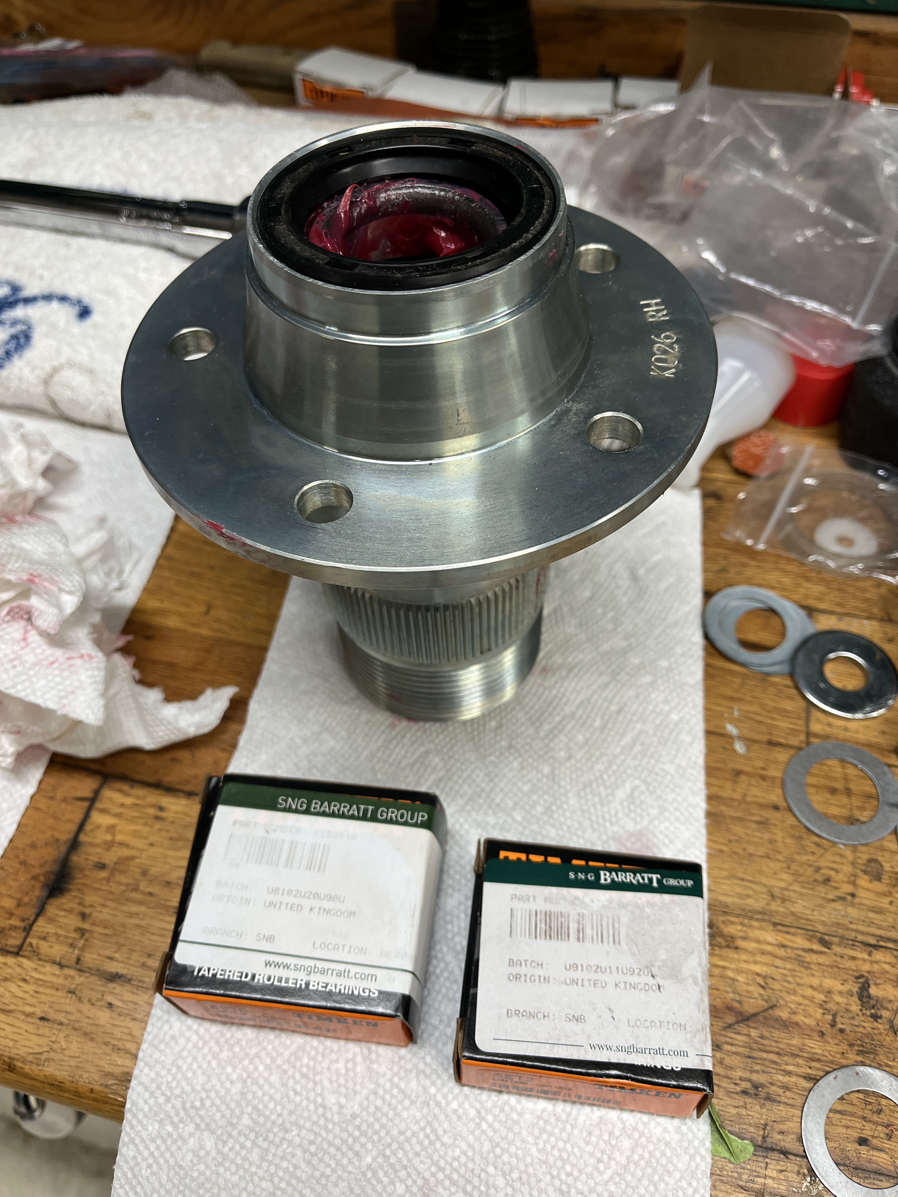
Here is a photo of the new splined hub. The splines that engage the wire wheels get worn so it is best to replace them. Plus, it is easier to press the races for the new wheel bearings into new hubs.

Here is the “glamour shot” of the final assembly. Those brand new brake discs are coated with something that keeps them nice and shiney. I will wait to the last minute to remove it!
As of this writing I am very close to finalizing the front supsension. I have ordered some 0.010″ spacers from SNG that are required to center the brake calipers on the brake disc. I am still looking for the short brake hardline that will connect that dangling brake hose to the caliper. I know I have it, I just can’t lay my hands on it. Typical!

Discussion
Comments are closed.