Recently I installed the engine in my 1963 Etype FHC project. A lot of preparation went into planning this “milestone” event, as discussed in the article here. Also, I had done a “test run” last year, when I installed a spare short block and Moss box transmission into the car to get weight on the chassis as required to evaluate panel gaps. So I knew a few do’s and don’ts from that exercise. Still, I made some new discoveries during my efforts.
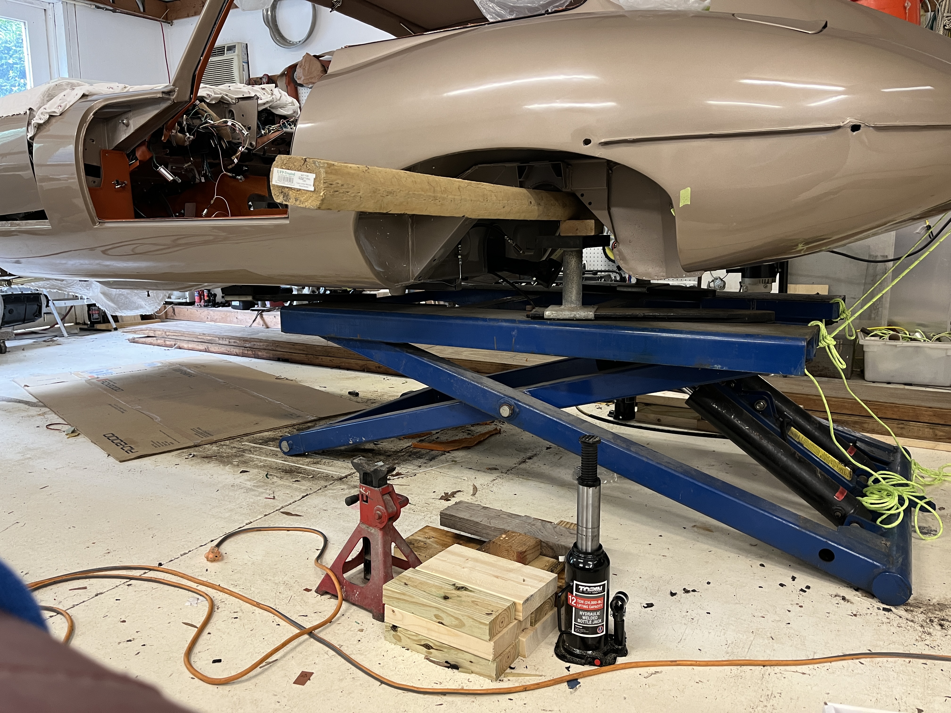
Let’s start with the fact that it is possible to install the engine “from the top” using an engine hoist. If you don’t have a lift that may be your best option. But I do have a lift and I am pretty sure that coming in from the bottom has to be easier, with less risk. I started by putting the body shell on temporary supports in order to allow me to reposition my BendPak mid rise scissors lift. BTW, this lift is excellent if your garage ceiling height is compromised. “Temporary supports” basically involved inserting long 4×4 posts across the car at the front and rear, supported by jackstands. This allowed me to lower the lift to the floor. This lift is not bolted to the floor so it can be repositioned, with great effort I might add. I have an electric hoist which I can use to “flat tow” the lift axially. In this case I moved it rearward until no crossmember of the lift obstructed the rearmost part of the opening in the cockpit for the transmission. This resulted in such a forward weight balance that I had to add some buckets of sand to the boot to keep the car from tipping forward. Here is a photo.

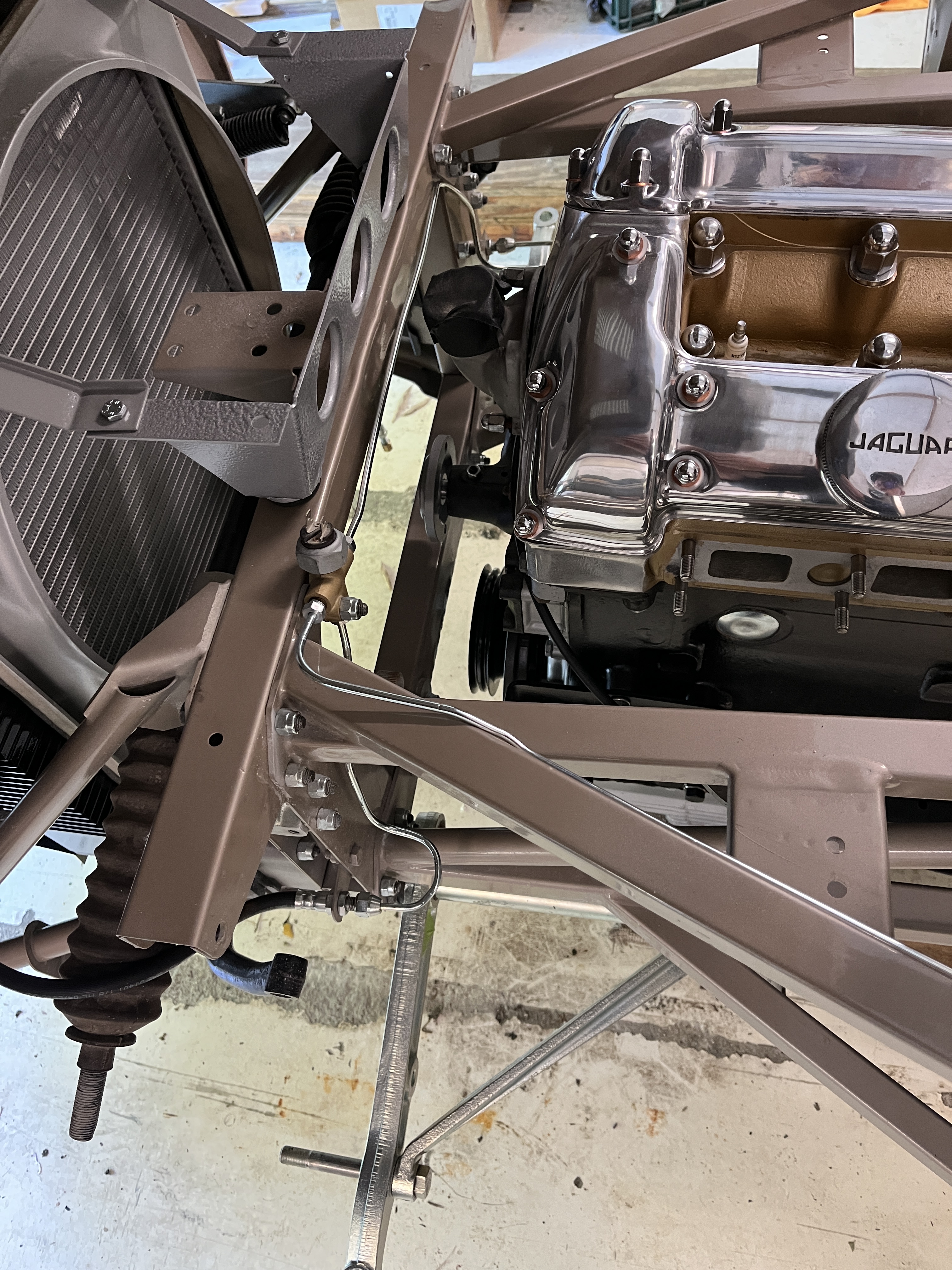
As discussed in my prep article, the motor mount brackets cannot be installed. You want the engine/tranny combination to at least be level on its dolly, and maybe having the tranny end elevated just a bit would be even better. There are 3 “choke points”. The body structure at the rear of the transmission tunnel (shown above), the picture frame, and the two sheet metal brackets where the reaction plate will attach.


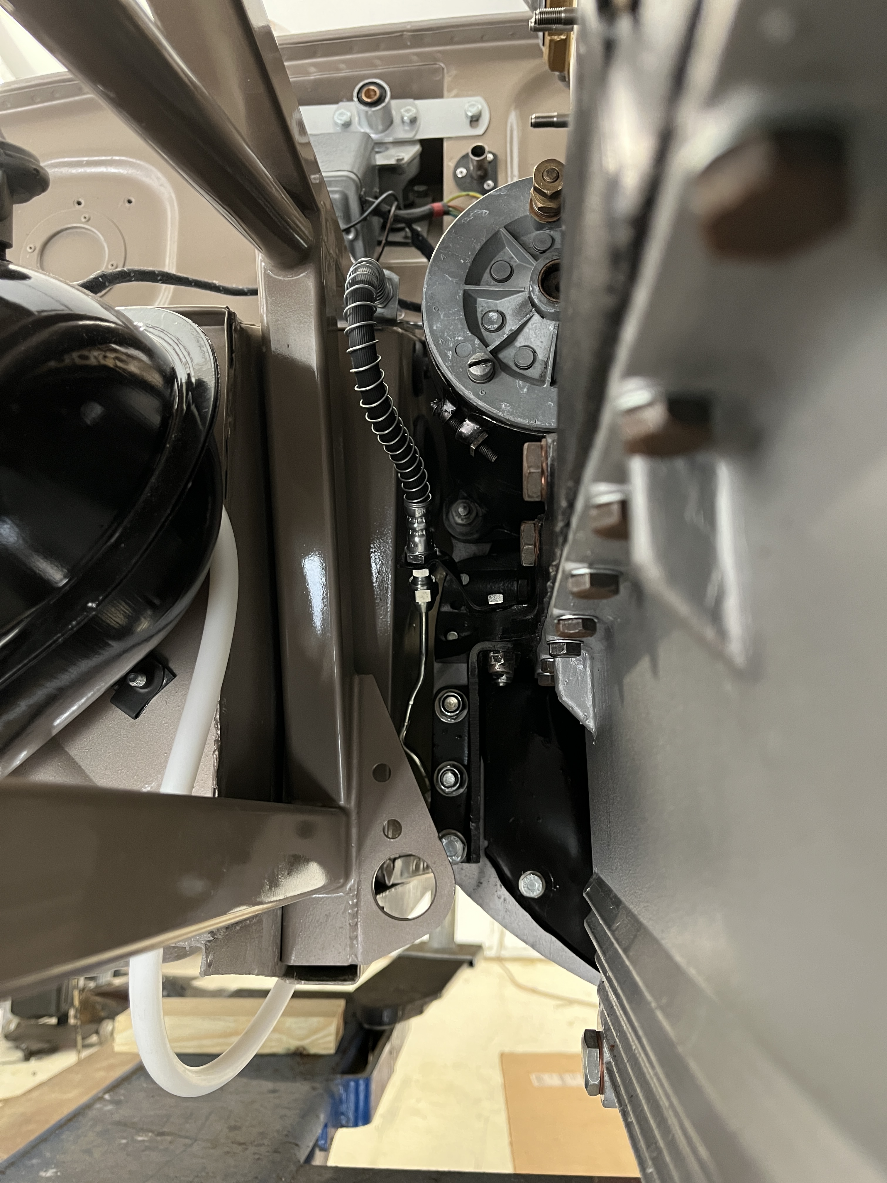
On the passenger side, there is an additional complication, that being the hardline leading from the clutch slave cylinder up to the spot on the side of the engine where it transitions to a flex line. I had this line on hand and had installed it provisionally. It became pretty clear to me that the line projected into the space I needed to lower the bracket through. So I took it off. Once I got the engine completely lowered into position and the front and rear mounts attached, I turned my attention back to this line. As many probably already know, there is very little room between the transmission tunnel sheet metal and the slave cylinder. So as I attempted to install the line into its fitting on the slave cylinder, I was finding it impossible to get a wrench on the fitting. And I have a collection of 7/16″ wrenches that are cut off very short, as reaching the bleed screw on the rear brake calipers on the IRS is also very tight. Which is why most folks recommend remote bleed screws for those calipers. I wound up having to release the rear mount, allowing me to lower the transmission as much as it would allow me. This gave me just enough room to complete tightening of the fitting. I think if you knew this situation was coming, you could be very aggresive about routing the brake line in this area to be clear of the bracket as it was being lowered. It is definately something to consider. Alternately, as soon as the body is lowered below this choke point, you might want to jump in there and install the line, at least the slave cylinder end. The end at the flex hose is pretty easy to reach even with the engine in its final position.
So that is one of my most painful memories but there are a few other things I learned. One is be sure and have your water pump and its pulley installed, if at all possible. I had the water pump installed but not the pulley. Later, I had to lift the engine at the front to get the pulley installed. In hindsight, I am pretty sure that having the pulley installed as you lower the body does not present a problem. Another thing, two thing really, are the tach generator and the support brackets for the stabilizing link at the front top of the bell housing. I think both of these cannot be installed as you lower the body, again due to the tight clearance at the reaction plate bracket. But once you do get the engine totally installed, both are very difficult to install. I took a middle ground. I left them off until I cleared the bracket choke point but as soon as I had cleared the choke point, I moved the engine forward to allow both of these to be installed. That worked out pretty well. Make sure you have test fit both of these pieces and that you have the holes thread chased and the bolts ready to go. Also make sure the bolts/nuts at the output flange of the transmission are ready to go. Finally, I installed the engine without the steering shaft installed but it appears that it could have been pre-installed with no issues. Conversely, you cannot install the steering shaft with the radiator and stone shield in place, so I would recommend getting it installed early in the game. I learned this the hard way!
As you lower the body, the engine will need to be forward such that it is almost touching the picture frame when you reach the point where the rearmost part of the transmission is clearing the body sheet metal. As I recall, the round plate that accepts the spring mount was the critical item. But once you get past this point (and install the clutch line, the tach generator, and the stabilizing links) you will need to move the engine to the rear, hopefully for the final time. You are moving it to the rear to line up the motor mounts, which aren’t installed yet. Once you get it fully lowered, you will want to install the motor mount brackets on each side, including the rubber inserts. You will adjust the engine front to rear as required to make the large bolt through the motor mount bracket.
You are almost done. I had all the pieces ready for the rear transmission mount, the main components being the spring and the trapezoidal plate that bolts to the bottom of the body. I jacked the rear of the transmission up until it would go no further. This was just enough to allow space for the uncompressed spring and the mouting plate to be installed with only minor pressure. Once you get the bolts made, check one last time that the spring and it rubber mounts are all centered and in their correct position. Then you can release the transmission back done. Reach inside the cockpit and make sure it is “bouncy”. If for instance the coils of the spring are collapsed, you have a bad spring and need to get a new one.

One of the last things I had to do was reposition the body on the lift, as with it in the install position and the weight of the engine added, it would have just tipped over if I tried to raise the combined assembly. I put the car back on temporary supports and drug the scissors lift forward, which allowed me to use a more traditional front lift point right under the motor mounts. Then I was able to raise everything up. Thankfully, there were no loud noises!

I think that is about it. If you did this every week, I bet you could do it in less than an hour. But even so, I think I got done in 3 hours or so. Or, according to the video I prepared and have linked below, in about a minute. It is a great feeling of accomplishment to reach this milestone!

Discussion
Comments are closed.