My 1963 Etype FHC would have been delivered from the factory with a Lucas battery that was connected with Lucas “helmet” type battery connectors. I bought my entire wiring harness from Rhode Island Wiring and, being authentic, it came with short leads for the negative and positive battery terminals. Note that this car is a positive ground car. Although many find it useful to convert their cars to negative ground, for authenticity purposes mine has remained a positive ground car. In this case, the heavy wiring connector to the negative post on the battery is a traditional stranded round copper cable, encased in a black insulation, leading to a heavy terminal on the starter solenoid. The positive post on the battery uses a flat braided cable that is not insulated and is most likely galvanized copper, as it has a dull silver color. It connects to a bolt on the outside of the drivers footwell bulkhead. I have been through several battery options on this car. But first some background, from the Factory Fit section of the excellent website forum.etypeuk.com.
The battery used on the 3.8 E-Type was a MILAM cased Lucas FRV 11/7A, 9 5/8″ x 7 5/8″ x 5 5/8″, 57Ah capacity, tar topped with separate Lucas branded black filler caps and six exposed round copper cored lead ‘links’ connecting the cells. The battery had Lucas lettering moulded on the side in black (not white or the 1970’s red and gold logo sticker!) and the filler plugs were black to Jaguar specification. Lucas did supply other batteries with red coloured plugs (made them easy to find when you dropped one) but not on the E-Type; probably an aesthetic decision by Sir William! It sat on a moulded ribbed battery tray made of black Bakelite with a spout for a rubber drain tube in the lower rear corner. Under the Lucas ‘helmet’ type battery connectors there were anti-corrosion felt washers, green for the negative post and dark red for the positive post. The Parker-Kalon self tapping screws holding down the helmet connectors to each terminal post were slot head (documented by a Lucas bulletin). Every Lucas battery was supplied with printed instructions beneath one of the plugs detailing maintenance instructions and specific gravity. Cars for export were fitted with Lucas FRVZ 11/7A ‘dry charged’ battery which required filling at the final destination – the instruction label was therefore printed in red. A fully charged battery should have an SG of between 1270 and 1290.
After being less than satisfied with the durability of several period correct looking batteries that I had previously purchased, I read the rules for JCNA concours competition and here is what I found.
- Batteries and Battery Compartments
a. Inspection
Entrants should be asked to remove the cosmetic or protective covers from the batteries. (Battery covers which are screw fastened or clamped to the battery or its hold-down should not be removed.) Judge the general area, the battery configuration, its style, cover, the positions and type of its terminals, the visible cables, the battery hold-down and the battery cable ends.
Note 1: Configuration refers to “maintaining the original type and placement of battery terminals.” “Size” was expressly deleted from the rule.
Note 2: XK 140 and XK 150 batteries are not judged because of their location in the wheel wells.
b. Battery Brand
Lucas and other batteries that were original equipment are considered expendable and may be replaced with a battery of any brand provided it is in the same location and orientation and has the same voltage and configuration as the original.
c. Battery Style
Fluted or cylindrical sided (Gates-Optima style) batteries are non-authentic.
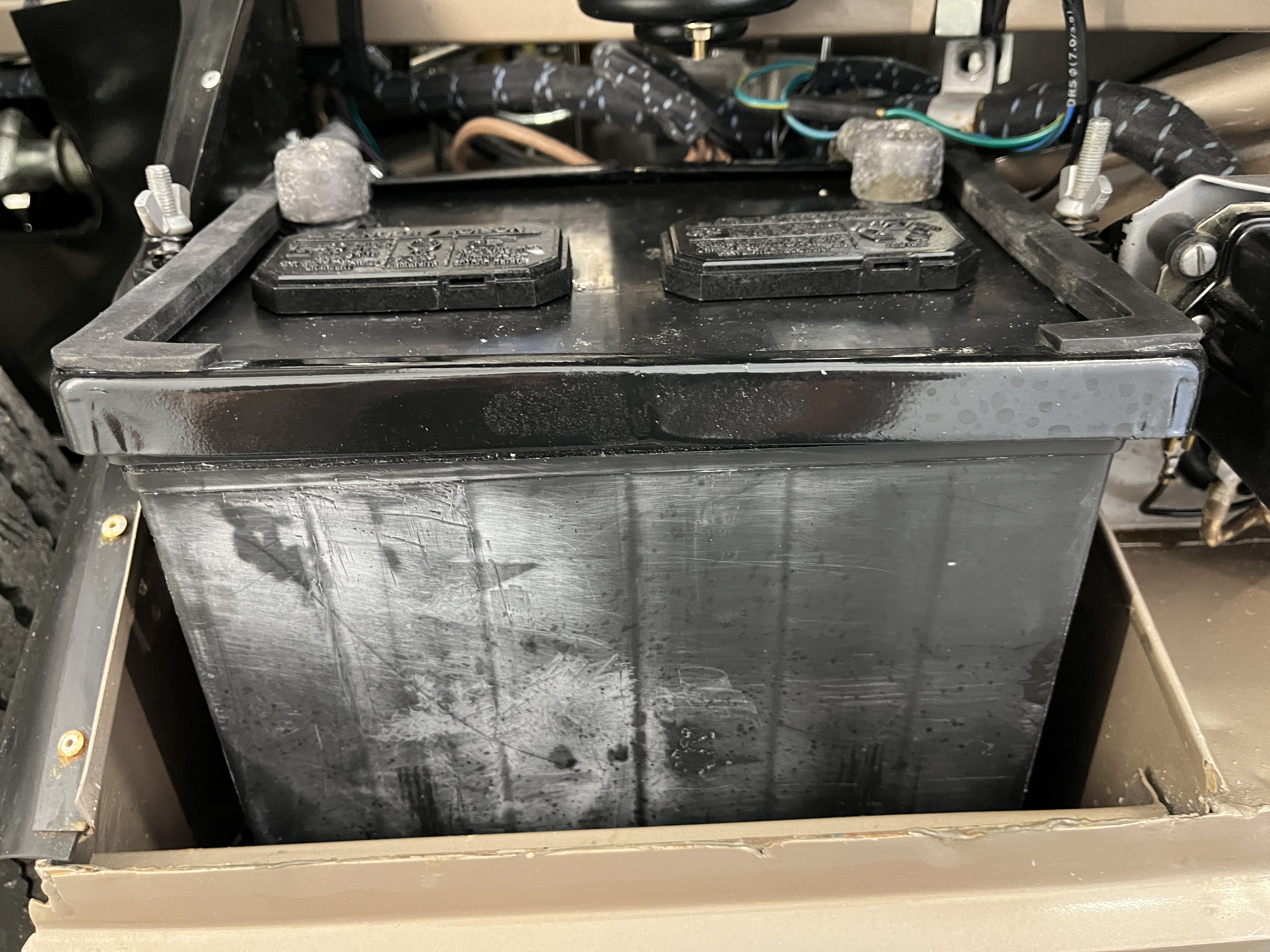
Reading this “set me free” to use a more modern battery. What I wound up with is Interstate battery MT-25. This battery fits within the available space pretty well. The positive and negative battery terminals are in the correct position. But there is always a “but”. The standard rectangular battery hold down bracket sold by SNG is slightly longer than this battery. Frankly, I had run across this problem with my previous period look batteries. I don’t know, maybe someone sells a bracket that fits but what I wound up doing was to reduce the width of the bracket by cutting, welding, grinding, and painting. I know most of you won’t want to do that but that is what I did. That said, if you stick with the stock bracket, the battery would still be secure, it would just look a little funny. SNG is pretty good about engineering their parts to be true to the original so I suspect the bracket they sell is sized for one of the original Lucas batteries described in the Factory Fit article above. There is a reason why I call this series Some Assembly Required!
I had experienced some electrical “gremlins” with this whole setup before, in that every once in a while, the starter would be balky. Just often enough to be annoying and cause me to carry a supplemental battery jump pack around with me. To digress, these are modern marvels. About the size of a 6″ Subway sandwich, they will give you extra starting boost when you least expect to need it. But I digress! So I wanted a modern battery. Nothing fancy, just a standard lead acid battery. The Interstate battery fit the bill. I removed the stickers and I sprayed the caps with black paint. It is very innocuous and looks perfect. Note that the Factory Fit discussion does not consider the red and gold Lucas stickers as authentic. As noted above, the JCNA rules are silent regarding this issue.
Due to the electrical gremlins, I really wanted the connections to the battery to be as solid as possible. One issue with the helmet style caps is that there isn’t much clamping action. A small screw through the top of the connector is all you get. And here is the rub. No batteries that I know of come with the battery post already drilled for this small screw. That is up to you. I consulted the wisdom of the Jag-Lovers forum on how to tap the battery post for this screw. Here is what I came up with. I removed both the positive and negative battery leads from the car. This is very easy. With the battery removed, both connections are at hand. I cleaned and deburred the helmet connectors and test fit them on the battery. A caution. On one period correct battery I had previously acquired, the post on the battery resulted in a loose fit of the helmet. As I recall, I had to remove material from the top of the post to get a good fit. After confirming that I had a good fitment of the connectors, I installed the helmet connectors on each battery post. I set the battery on the platform for my drill press. The holes in my caps were not exactly centered on the post! So you want to “clock” your wires/cap in the same direction as it will be on the car. I started with a shallow cut using a drill bit the same size as the the hole in the connector, just to establish a center. Not a center of the post necessarily but a center of the hole in the cap. Then I used a drill bit that was just a little bit smaller than the screw to drill the post on the battery. I used cutting fluid. This drilling operation generated some chips but the drill did not pull down and jam. So that went well. Also, by having the cap in place, the hole was lined up properly. By the way, the size of the drill you want to use is somewhat critical. If you look at any screw thread from the side, there are two diameters at the threads. There is the diameter at the OD of the threads and the diameter at the “root” or bottom of the threads. When installing say a sheet metal or wood screw, you generally pick a drill bit that is smaller than the root diameter. The the screw cuts its way into the material the first time you install it. As pointed out by a Jag-Lovers expert, the lead post behaves a little differently. It doesn’t want to be cut. Rather the lead is displaced to match the profile of the screw thread. It sounds like splitting hairs but you kind of want the diameter of the drill bit to be half way between the OD and root diameter of the screw. This is actually pretty important. Too small of a bit and you will never get the screw installed the first time. Too big and insufficient threads are formed. I hope that doesn’t keep you awake at nights but it is key to the next step.
Getting the screw to cut its initial threads was still a challenge. I ran the screw in a little bit at a time, and then removed it to clean it off. As noted above, it does not really cut and generate chips, it just deforms the lead. I used cutting fluid. As it got close to the required insertion, turning the screw got pretty hard. Fortunately, nothing snapped but I was really on guard not to twist it too hard. Once I got the screw in the initial time, it runs in and out pretty well, especially with the cutting fluid on it. Blow the hole out with compressed air as you go and just wipe some cutting fluid on the screw. Don’t fill the hole with cutting fluid or you may get a small “hydro lock”.
So the battery is installed and the starter cranks. Remember, I’m the guy with the balky starter so I was pleased that that issue did not rear it’s head, at least for now. I added a dedicated cable from the battery ground to the block, which I think is the silver bullet. We’ll see.

Discussion
Comments are closed.