As discussed in other articles, starting here, I have been rebuilding the M97 engine of my 2007 Cayman S. One reliablity upgrade that I did was to purchase a new engine wiring harness from Porsche. I did this for several reasons. It is a 5 owner car with little maintenance history. I can see that the harness has been hacked. Also, I feel that there is a point, which I cannot objectively identify, where wiring harnesses start to age out. It can be subtle. Increased resistances on the wiring path to sensors can cause the expected range of sensor values to shift subtlely. Remember, this is an analog car. Very generally speaking, sensors take a nominal 12volt system operating voltage, carve out a range from 2V to 10V, and make ECU decisions based on the percentage voltage returned in that range. Add in a few ohms of wire resistance and the values are no longer representative of what is actually happening. Catostrophic? No. Annoying? Certainly. Anyway, as I was laying in my new wiring harness, I realized that this was a good opportunity to shoot some video to talk about the locations of sensor and components on the engine. And also talk about the types of terminal end clips that are used. Trust me, it was frustrating as I removed the engine to determine just how I should approach each clip to get it to release. I must admit that I broke a few, just not really understanding how they worked. If nothing else, this video will give you an idea regarding how each clip is designed with regard to releasing it from its sensor or component.
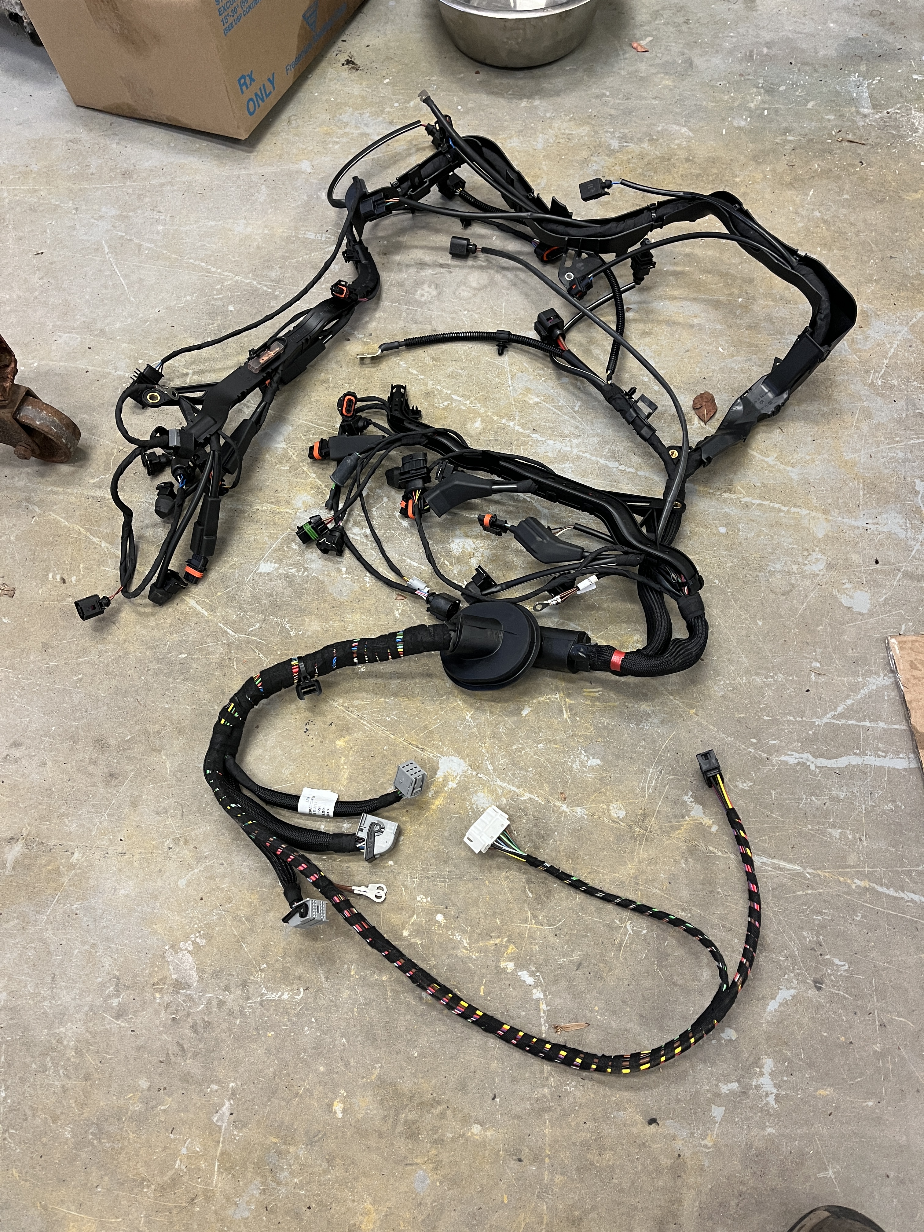
Here is a photo of my new wiring harness.
So, since a picture is worth a thousand words, and a video consists of thousands of pictures, below are the links to a part 1 and part 2 video I did on sensors and components. If you come across this post looking to identify a specific item, note that I have added subtitles that you can view as you fast forward through the videos. Spoiler alert. The crankshaft sensor wound up at the very end of the second video. I probably should have done it first!
NOTE: At 3:20 in the following video, I discuss the location of the solenoids for Variocam and Variocam +. I have discovered that I stated it backwards! The solenoid for the Variocam (inlet valve active advance mechanism) is on the left in the video. Easiest to remember is that it is the one closest to the end of the cylinder head.
I don’t think I mentioned it in the video but there is a small in-line valve that is a switch to bring in the fuel vapor from the carbon canister and inject it into the inlet manifold immediately downstream of the throttle valve. It is hard to see but it is immediately behind the #5 intake runner. Its harness connection is the wire clip type.
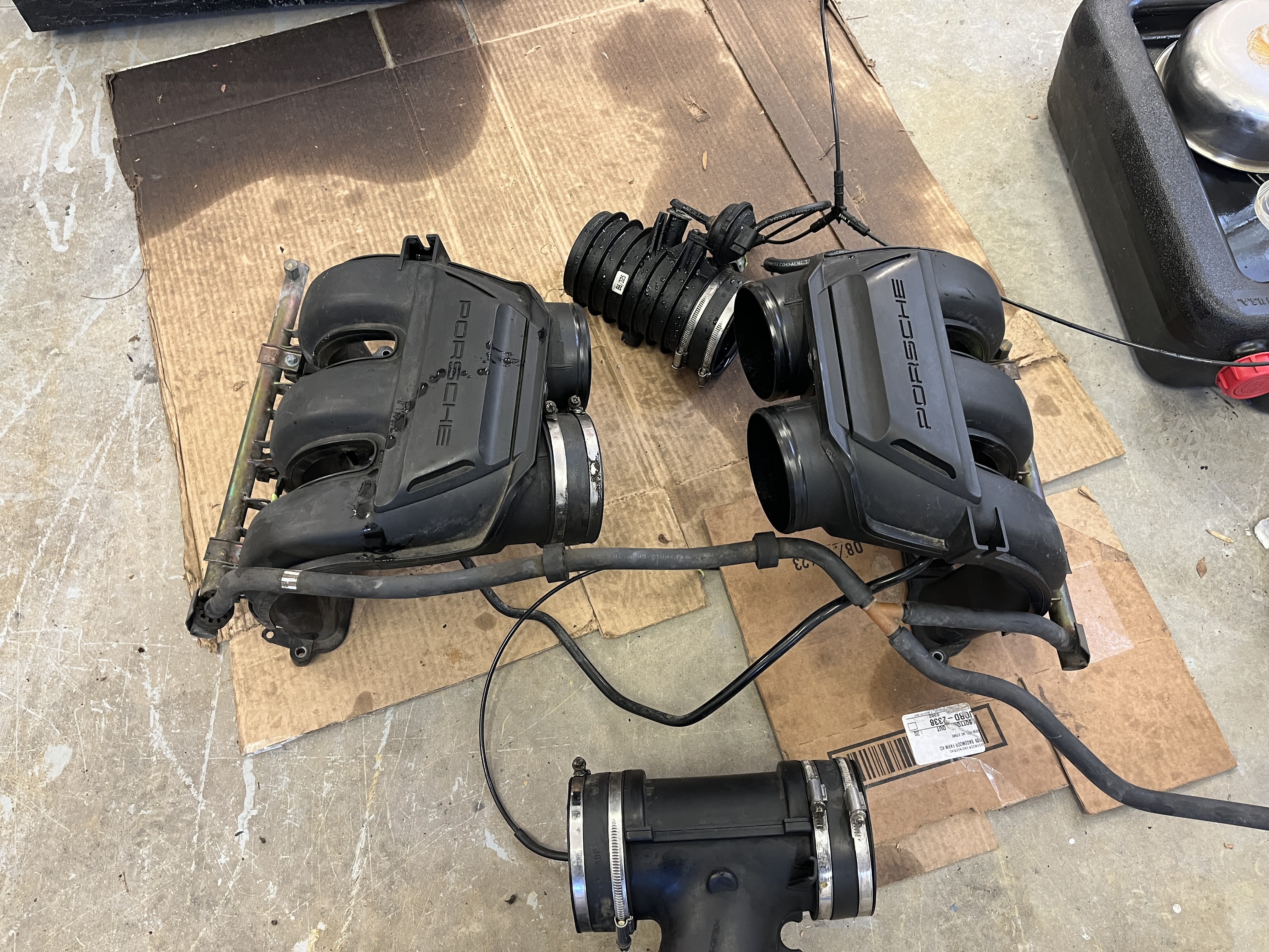
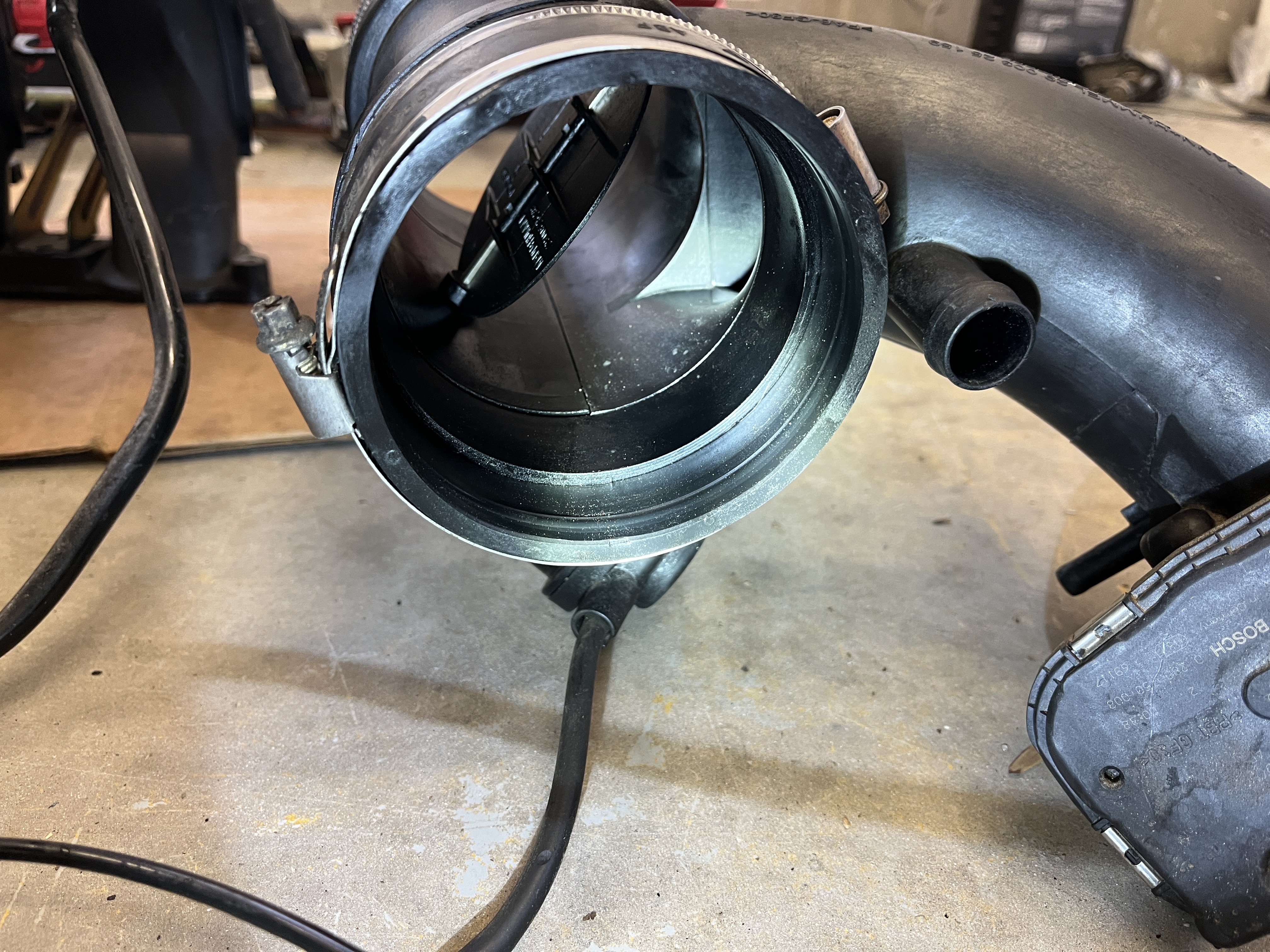
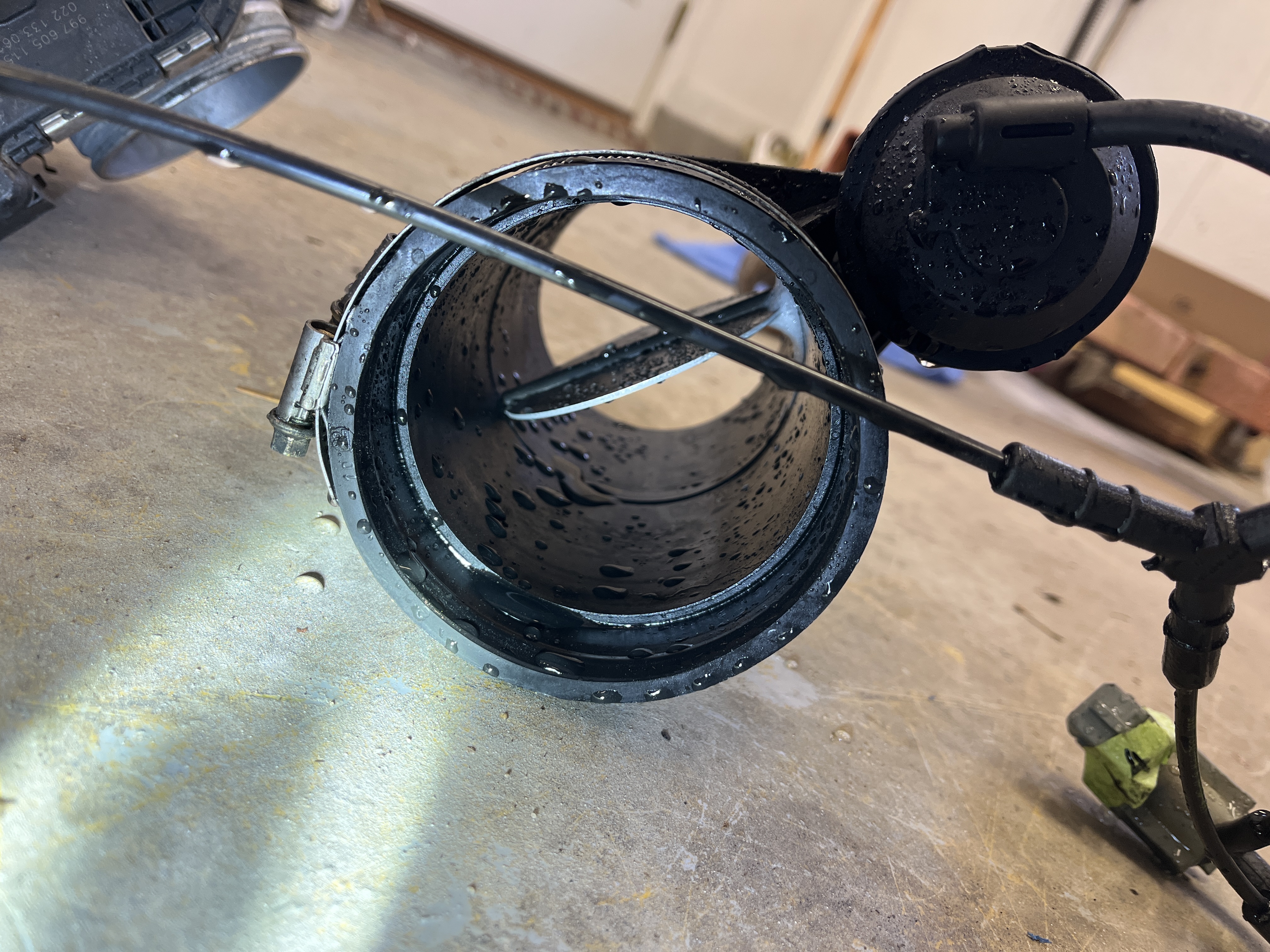
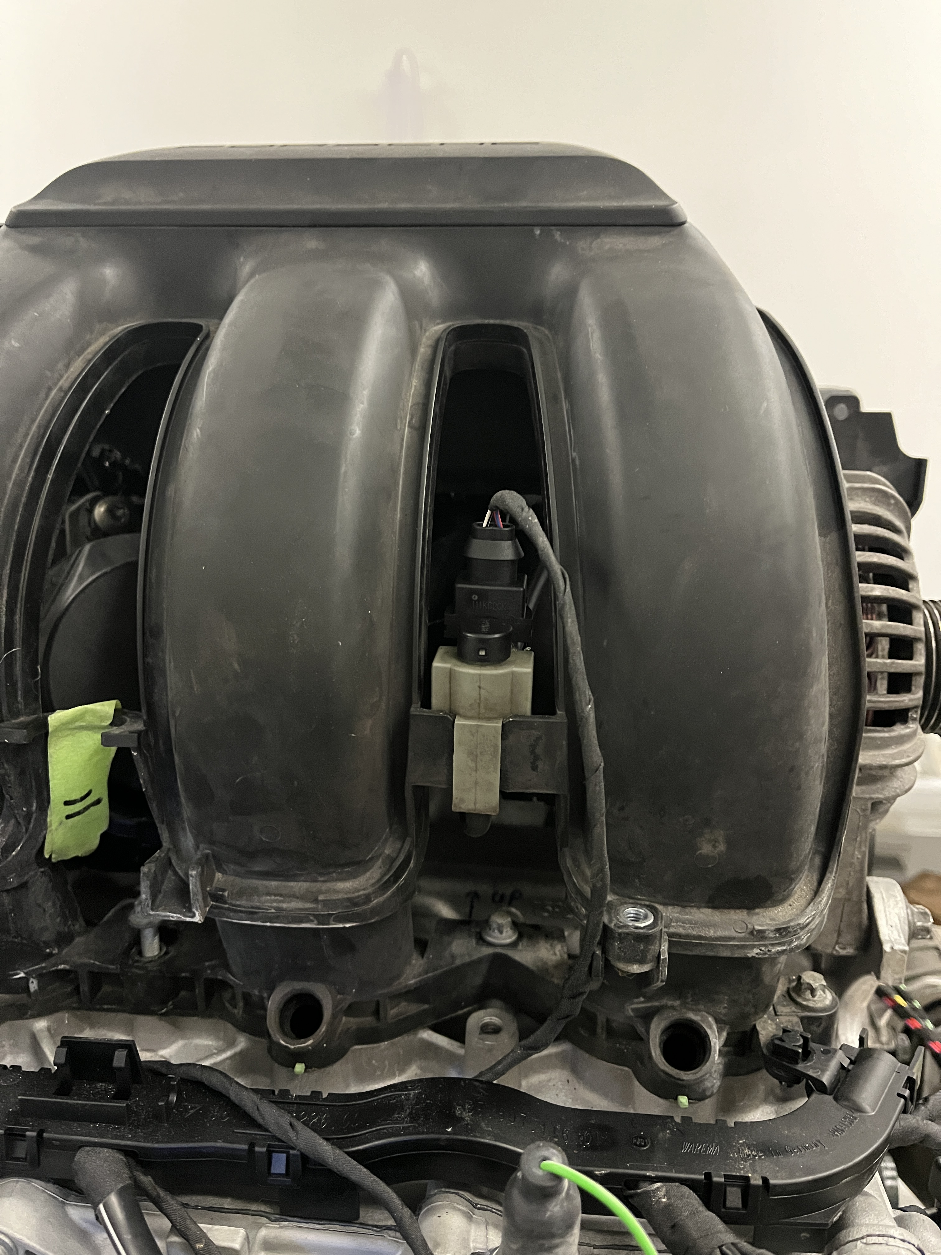
As a bonus, I’m going to do a quick tutorial on the “resonance flap valves”. Probably most of us don’t even know that they exist, as they are hidden. Very basically, there are flap valves in the intake plenum, very similar to throttle valves, that serve to close off the two halves of the engine, such that it “breathes” like two independent 3 cylinder engines. Although this is just an educated guess, Porsche closes the flaps during low rpm/low load conditions, in order to improve emissions performance. Of course, the real fun starts when the flaps are open, allowing optomized cylinder filling during high speed operation. This is a complex subject but very generally, pressure pulses are generated every time an intake valve closes. These pulses bounce around the plenum. When strategically designed, a pulse can arrive at another intake valve just as it is opening, serving to ram extra intake air/fuel mixture into that cylinder. BTW, headers with equal length tubes do the same on the exhaust side of things. The resonance flap valves are activated by vacuum driven “change over” valves, which are controlled by the ECU. Here are a few pictures.


Anyway, I hope this will help you out when you think you need to locate a sensor or component for replacement. Of course, everything is harder to see looking down into the engine in its compartment but if you know what you are looking for, that certainly helps!
The next article in this series is Engine Re-Assembly Part 2.
Bonus content- Here is a short animation that shows how lifters work. I always thought of them as “pumping up” but yes, there is also a “pumping down” action.
More bonus content- engine oil level sensor- Starting with the Cayman/Boxster/911 around 2006, Porsche did away with a dipstick. Oil level is measured electronically. There is a sensor “stalk” that is screwed into the top of the block and extends down into the oil sump. If I understand it correctly, the resistance of the sensor changes depending on the depth of the oil. The sensor also measures the temperature of the oil, although this is not reported on the dash gauges. If you own a Cayman/Boxster/911 from this era, you are familiar with the digital readout on the dash, with “bars” showing the oil fill level. You may have also noticed that in some cases there is a time delay before the oil level is reported. I have yet to find any Porsche documentation of how this works, in detail, but here is a discussion I found in one of their technical documents.
Oil Supply/Oil Level Measurement – 911 Carrera/S
(997), Boxster/S & Cayman/S (987)
The oil supply system as a whole has been adopted from the previous models. A change applies in the area of oi level measurement. Continuing with the positive experiences with electrical oil level measurement and a changeover in measuring habits away from manual measurement via the oil dipstick to electrical oil level measurement, the new engines do not have an oil dipstick.
The hole on the crankcase for the oil dipstick is closed with a plug. In order to speed up the process of measuring the oil level in certain operating states and in the interests of measuring convenience, map compensation has been introduced. Previously, all of the engine oil had to return to the oil pan after the engine was shut off before the oil level could be measured. To enable accurate measurement of the oil level, the necessary time required to achieve this state was ensured by means of a waiting time for oil level measurement, determined according to the oil temperature and the length of time the engine has been off. With map compensation, the actual measured oil level in the oil pan is compensated to take in account the oil temperature and the length of time the engine has been off. The oil that has not yet returned to the oil pan is electronically calculated and theoretically added, and the calculated oil level is displayed in the instrument cluster as quickly as possible. This results in a substantial reduction in measuring times compared with the previous system.

Discussion
Comments are closed.