Previous articles in this series – Engine Assembly Notes Part 1 and Tour of Engine Sensors and Components
Picking up from where I left off here, this is a continuation of the assembly notes I compiled. As discussed in the previous articles, I leaned heavily on the Jake Raby M96/97 Engine Assembly video series and, to a lesser degree, the Porsche shop manual. These notes are items that I felt were poorly explained or I picked up via the school of hard knocks! Brandon at Slakker Racing did provide valuable input at key moments. Although I tried not to pester him too much, he has been very cheerful about answering my questions.
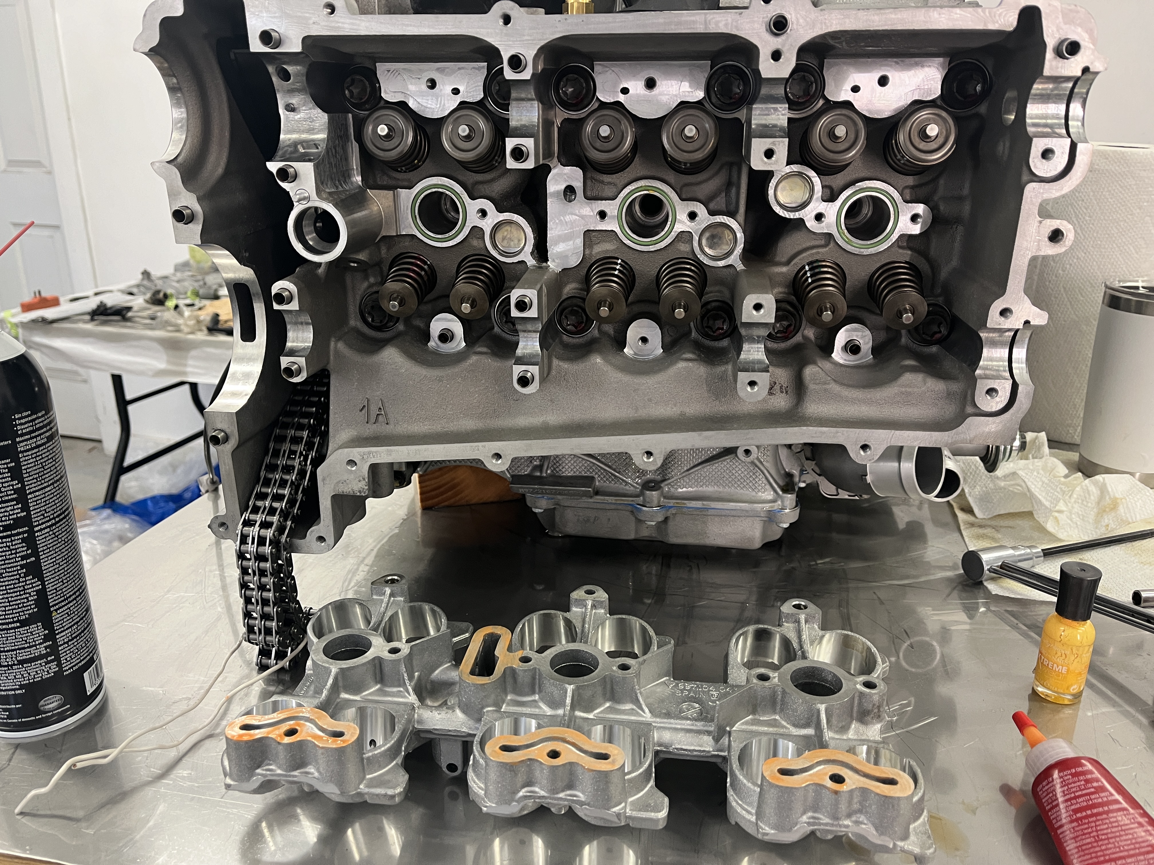
- Installation of tappet housing (lifter carrier). Upon the advice of Jake Raby’s video and noting that my engine had 100K+ miles, I decided to replace the tappet housing. Not cheap. My local Porsche dealer “price matched” the on-line price from Silver Springs Porsche. The carriers came from Germany and with expedited shipping got here in about 10 days. I would tend to agree with Jake in that the housing is an aluminum alloy whereas the lifters are a hardened alloy steel. It is hard to quantify the wear on the housing bores without specialty equipment but visually it was easy to see wear areas due to the side loads placed on the lifters by the cams.
- Check your lifters. I had removed all my lifters and placed them upside down in labeled paper cups. Before re-installation, I decided to give them a “squish test”. For the exhaust lifters, you put it upside down on the bench and push on the central button. All but 3 were very firm when I did this test. Some internet sleuthing determined that firm was good. Then I took the 3 that squished (easily depressed multiple times, about 3/8”) and put them in an oil bath to try and firm them up. This did not help. Finally I removed the central assembly by pulling really hard with a pair of pliers. I cleaned them up as best I could and re-assembled and tried to pump them up in an oil bath. No joy. I finally bit the bullet and ordered 3 new ones from the dealer. These were firm right out of the box. For the more exotic Variocam+ intake lifters the test seems to be the opposite. You should be able to push down the center button from the top side. I tested all of them and all I can say is that they all felt the same to me. Since they are so expensive, I called them good to go. I cleaned all the lifters up and installed them in the carrier as per Jake’s video instructions. Edit- during my initial startup and break-in, I have not heard any lifter noise. Yay!
- Manage your timing chains. Jake’s video in several instances discusses dropping the loose timing chains down in the timing chain well to get them out of the way. I’m sure he has done it many times but this caused a problem for me. When I got ready to hook up the timing chain on Bank 1 over the exhaust cam, it was clearly a small amount too short. There was not enough slack to install the drive gear. After much investigation I determined that the chain, down at the IMS drive gear, was partially on and partially off the sprocket. Due to the geometry of the case in that area, I could not get it to feed correctly onto the sprocket. At least, not until I carefully removed the IMS bearing cover, which allowed that end of the IMS shaft to move slightly away from the crankcase. At that point I was able to engage the chain correctly on the sprocket. I then re-engaged the bearing cover, all the time worrying that I would hear a cracking sound from the other end where the oil pump console had cracked. Fortunately this did not happen. I conservatively ordered a new seal, M12 locknut, and M6 bolts to permanently re-install the bearing cover. Both the M6 bolts and the M12 nut are micro-encapsulated. After installing these, I was back in business. The chain slack was correct and I was able to proceed with installation of the exhaust cam shaft. In retrospect, I would try and keep the timing chains somewhat taut at the IMS sprocket end. I did this simply by making some simple restraints out of wire.
- The Timing Procedure- I was able to following Jake’s procedure pretty well. I had purchased a set of tools from LN Engineering for setting the timing. This included the tool that you insert on the ends of the cam shafts to confirm they are in the right position. It also included the pin you stick in the crankshaft pully. It did not include the temporary bracket that he uses to hold down the end of camshafts away from the drive gears. I made one out of oak, which worked fine.
- Rotating the Crankshaft During the Timing Procedure- Maybe I missed something but I swear in Jake’s video, he had you rotating the crankshaft on Bank 1 with the exhaust cam gear prematurely tightened. This will make more sense when you are following the video. As he says multiple times, until you are done with Bank 1, you only get to rotate the crankshaft with the intake and exhaust cam shaft gears “loose” i.e not turning the cams. Just keep an eye on this concept and don’t follow the video blindly.
- Check your work!– After I got both banks timed, I decided to check to see if the firing order was correct. The way I did this was to use my compression gauge to identify TDC compression stroke on each cylinder. Even turning the crank by hand with a wrench, you get about 15 psi “bump” on the gauge at TDC. So the idea was to start on cylinder one, get the “bump” and then continue rotating the engine and checking for the bump at the other cylinders. The bump should follow the firing order published in the workshop manual. Well, this concept immediately went south when I couldn’t get a bump out of cylinder 1. To make a long story shorter, one of the intake valves was not fully seating. I verified this with a leak down tester. Air was hissing out of the port at TDC. So, bad news but I’m glad I caught it at this relatively benign stage of the build. I removed the head and sent it to Slakker, where they confirm the situation and rectified it. With the reworked head in place, I got a bump on all the cylinders, in the correct order.
- A Jake trick, not in the video- I saw a Jake trick that is not addressed in the video. He said to take a used scavenge pump oring and put it in the oil return slot at the aft end of the camshafts. This will keep the RTV that you use to seal the cylinder head cover out of the groove. Once you set the cylinder head cover, you can pull the oring out. Neat!
- Inspect your scavenge pumps – Something I saw on the internet that left an impression. The guy opening up a scavenge pump and found it to be failed. I don’t remember the details but I took the covers off mine and at least made sure the key components were all intact.
- At this point, I had the “long block” complete- Following are a few things I found building out the rest of the engine.
- Consider getting a new wiring harness- Yeah, I know, they are expensive. The good news is that you can still get one from Porsche. Think about it. This is still an analog car in the sense that the ECU has to make a lot of critical decisions based on the data determined by parsing voltages generally between 2 and 10 volts (a standard range for sensors). So let’s say your wiring harness has built up some resistance in a key wire and it adding a voltage drop of say 2 volts. Wow, does that upset the equations! Not to mention all the connectors that have had their retaining clips broken off. And the part of the harness that has been cut into by previous mechanics trying to trace an issue. So yes, I got a new wiring harness and am very glad I did. I spent a lot of time referring to the wiring diagram for the engine and making sure I knew where each connector went to.
- Consider getting a new fuel rail and lines- Another one that I would suggest replacing. This comes from my perspective of owning 944s and 928s. The fuel lines get very brittle, fail, and burn the car down. Best to nip this tendency in the bud.
- Consider getting new (whatever)- Getting new parts can be a slippery slope and an expensive one. That said, these cars are approaching 20 years old. There are a lot of electro-mechanical items that could be nearing the end of their lifespan. You just don’t know. But after you went to all the effort and expense of rebuilding the engine, it would be nice to know that some minor part isn’t going to ruin your day. I’m going to include a pdf of my parts list. I was generous. For sure, replace those crap corrugated tubes that run across the top of the engine and feed the AOS. Mine broke off in my hands when I took the engine apart. Regardless, there is no way you could spot a crack in this thing. Best to go back with new ones!
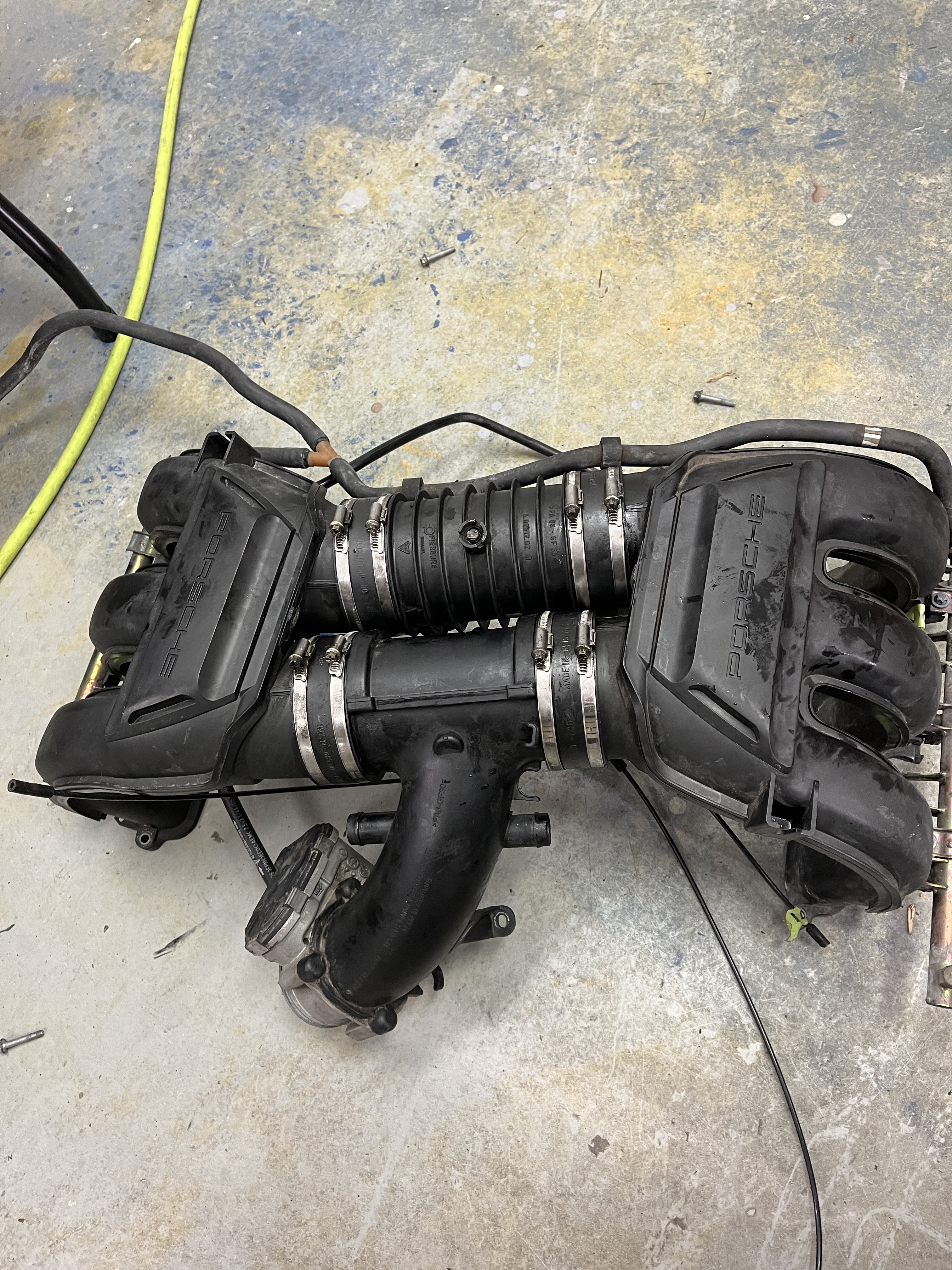
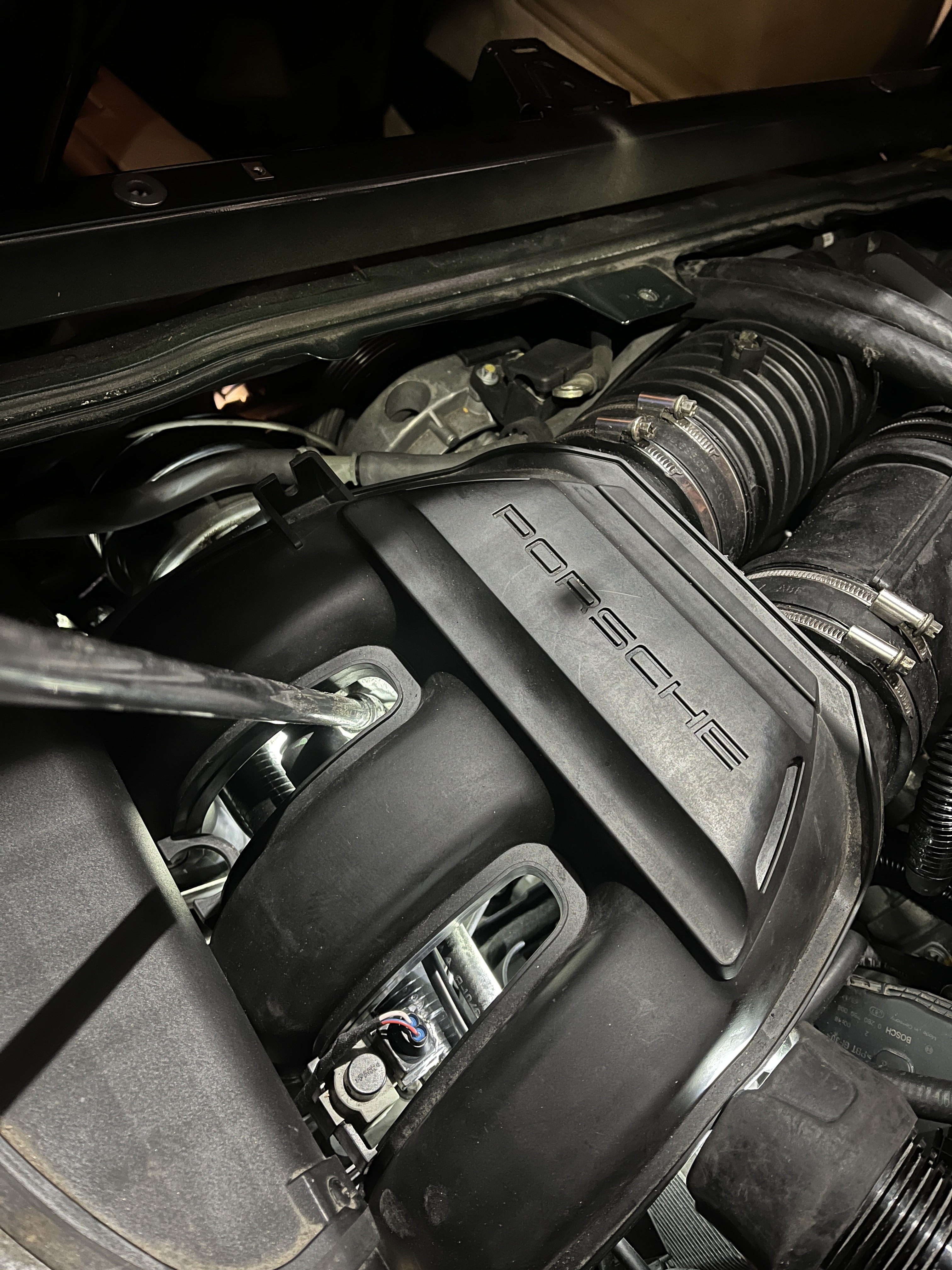
- Intake manifolds- So you have two halves, held together with rubber connectors and hose clamps. It’s a little bit of a “greased pig” to assemble. As I recall, I assembled the two manifold halves on the bench, with the hose clamps tight. I then carefully placed the manifold onto the top of the engine. Of course, not all of the attachment bolts lined up. But at this point, I could selectively loosen the hose clamps and adjust the manifold to line up. Once I got it lined up, I loosened all the clamps and then re-tightened them. Hopefully this left the rubber connectors relatively stress free. And yes, I bought new rubber connectors. There’s nothing worse than an unidentified vacuum leak at one of these connectors!
- Belts and suspenders- Probably a little late to mention this but, as Jake says, I torqued all fasteners to value. On all the smaller fasteners, I also put a dab of Locktite Blue on the threads.
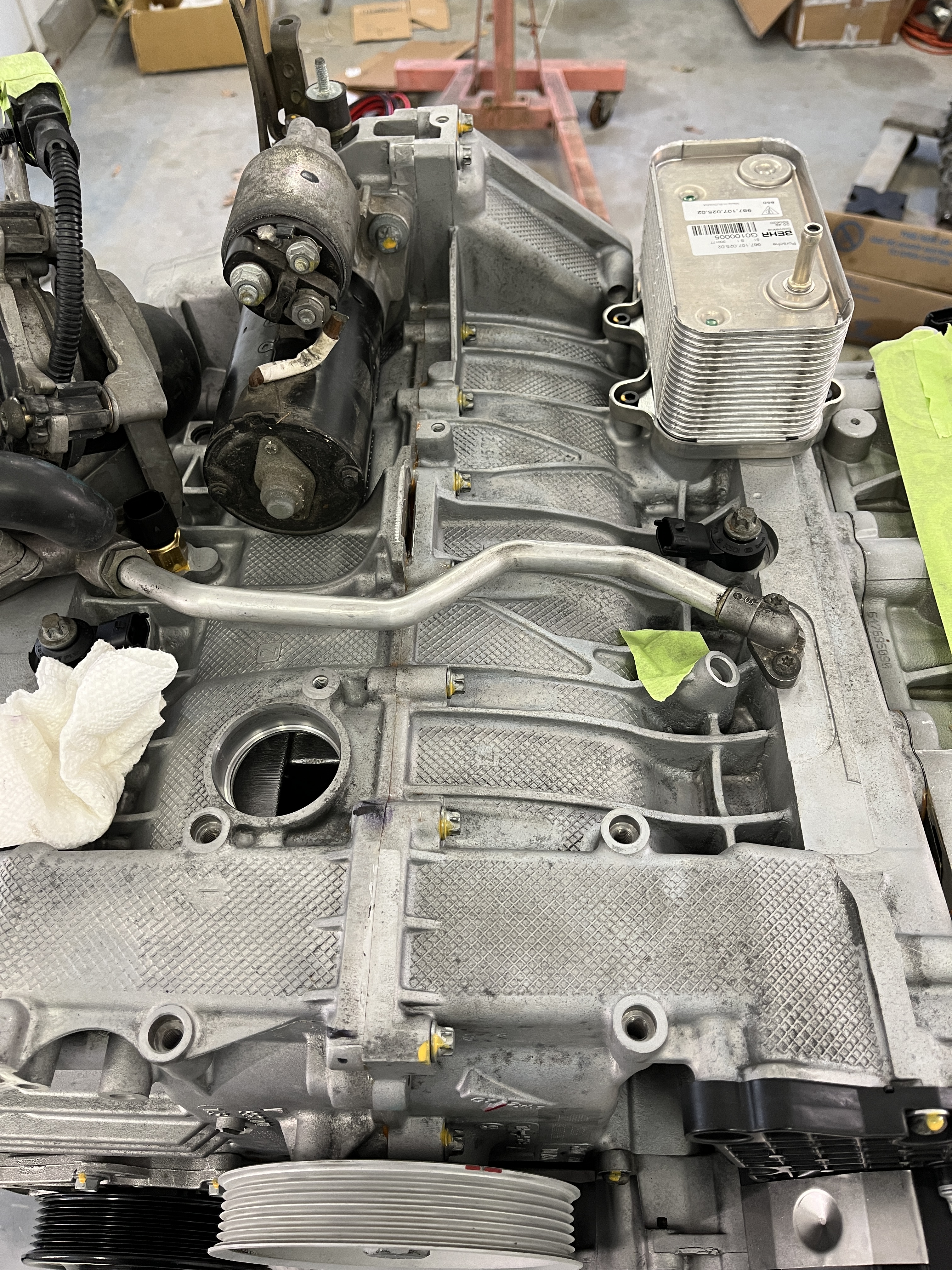
- Getting the engine ready for installation- There are a number of things that you will want to do in advance of putting the engine back in the car. Following are some suggestions:
- Identify and tag all wiring harness terminations that will be made after the engine is installed. Don’t forget the B+ line from the battery and the large ground cable that attaches at the front of Bank 1.
- Get your coolant piping in order. I replaced anything that was a “rubber hose” in the space between the front of the engine and the back of the firewall. This would include the two large coolant pipes, as well as two smaller lines that feed the heater circuit. And there are several rubber lines that go from the fill point in the rear compartment over to the coolant reservoir, that are hard mounted on the right hand side of the engine compartment. Take a close look at all the lines in this area. There will never be an easier time to replace them!
- Identify and pre-position- The fuel line, the vapor return line, the two lines from the power steering pump, and the line that attaches to the cam driven vacuum pump. Attach the line that attaches directly to the back side of the oil fill console. There is a “field joint” at the back of the engine, near the AOS, that you will use to make the final hookup after the engine is in the car. On the transaxle, the connection for the clutch hydraulic line. This line can get snagged as you lower the car so just keep an eye on it.
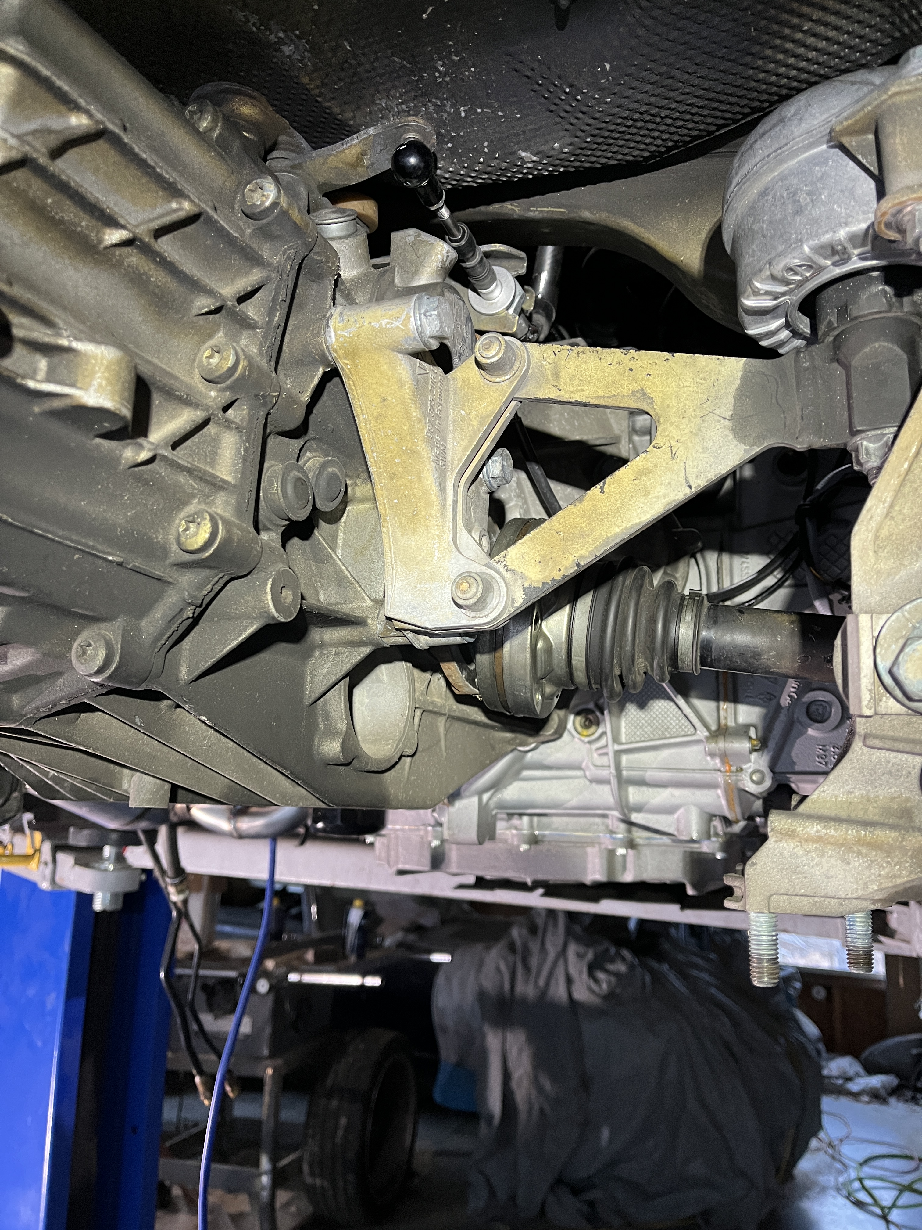
- There will never be a better time to replace the fluid in your transaxle. Also, evaluate your CV joints. Also, there will never be an easier time to replace the two transaxle rubber mounts as well as the rubber mounts at the front of the engine.
- I did not install my exhaust manifolds/cats/mufflers prior to installing the engine. I did install the front motor mount, such that the horizontal bar with 4 elongated holes was in place and ready. This bar engages the 4 studs in the engine compartment such that after you get the engine into final position, all you have to do is install the 4 nuts. I found that it was best to not install the two brackets and mounts on the sides of the transaxle until after the engine/transaxle were in their final lowered position. Access at that point was still good.
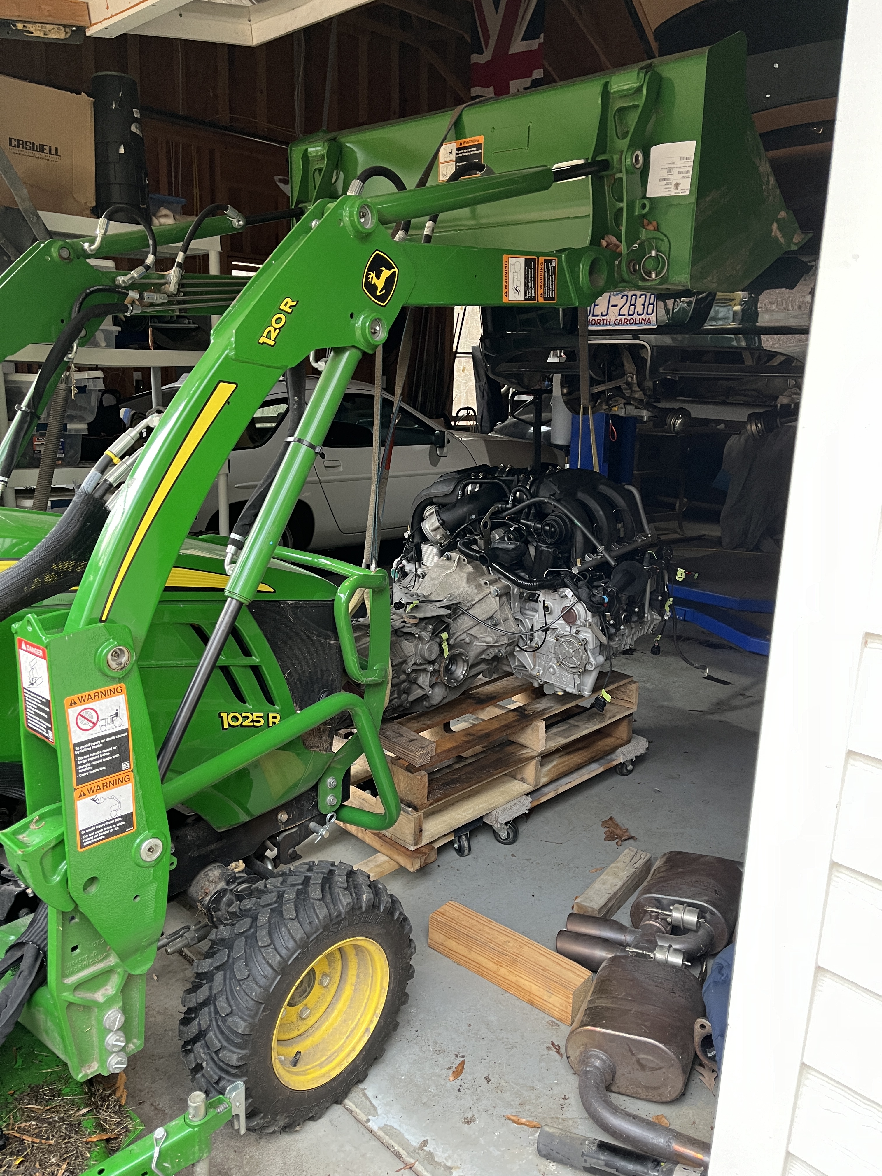
- Installing the engine- I sat my engine on a little “tower” consisting of two furniture dollies with two cut up pallets on top of them. The pallets get the engine far enough off the floor that there will be room to get in under the car and make the connections. I am of course lowering the car body down onto the engine, although I guess there is a world where you raise the engine up into the car, using something like a hydraulic table as used to work on motorcycles and ATVs.
- When you get the engine within 6” of its final position there are a lot of things to start looking at that will make your life easier. I found out the hard way! In no particular order: Consider hooking up your clutch slave cylinder hydraulic line and bleeding the clutch. Also consider hooking up your shifter cables. Especially on the drivers side, things get pretty tight in there. Double check your fuel line, vapor return line, vacuum line, power steering lines, coolant tubes, wiring harness, etc. as you get close, to make sure they are jamming or snagging. I’m not sure where the best place is to disconnect your inlet manifold. I did mine with the flexible rubber piece between the air mass meter and the throttle. There doesn’t seem to be a good solution. But start looking at this as the engine gets close because once it’s fully landed it gets really hard. The AC compressor is another one. I think because the hoses have to lay in behind the alternator and the power steering pump, it is best to get them into position as early as possible in the process. And speaking of the power steering pump, the shop manual had me take off the reservoir before pulling the engine. Probably to be able to get to one of the bolts on the AC compressor. Both the battery connection and the reservoir are vastly easier to reach before the engine is fully landed.
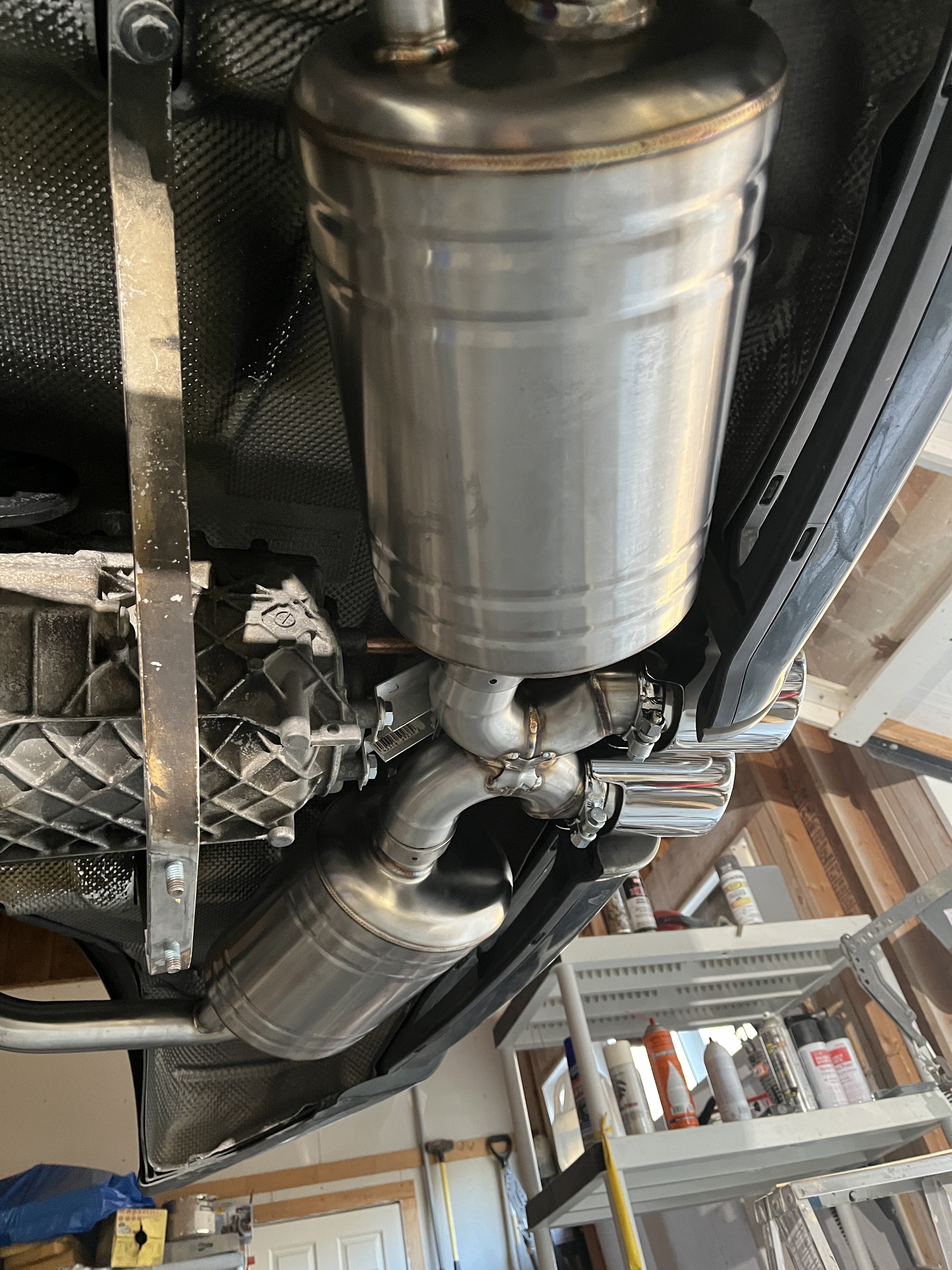
- Once the engine is landed, I was able to follow the shop manual. The shop manual has a pretty good order of assembly discussion once you get the engine landed. I did loose a day with my Top Gear exhaust system, which came with nothing useful to allow me to attach the mufflers at the back of the transaxle, as the stock system is done. I had to do some fabricating. In general, you put in the lower suspension reinforcement items, hook up the various electrical connections, install the serpentine belt, fill the power steering with fluid, fill the coolant system with fluid (you will need the vacuum install device), double check your oil level (more on that below). I’m sure I’ve forgotten a few things!
- Well, actually! Actually, I didn’t want to do all of the above and then find out the engine wouldn’t start. So I installed just the exhaust manifolds/cats and did not install the serpentine belt. Hooked up the battery and the B+ line, the ground, the fuel line, and obviously all the electrical connections to the ECU and the relays. And then came the butt clenching moment of truth. It cranked. It tried to fire. And then it fired! Wow, what a moment! I ran it just for 30 seconds or so but that was enough to make it an extremely good day!!! Then I did all the stuff in the previous comment. And tried it again. Another successful start!
- A 60 minute wait to check the oil level? So yes, when I connected up the battery and switched on the ignition, I got a PSM warning (which you can ignore), an ABS warning (which I also think you can ignore), and a check engine light. What I really wanted to check was the oil level, as I had done a “short fill” due to uncertainties of the Hartech deep sump and a totally dry engine. The dash display started a 60 minute countdown. WTF? After some reading on forums that led me nowhere, I decided to turn the key on and let 60 minutes expire. I put a charger on the battery just in case. After 60 minutes had passed, the oil level display did indeed come up. It was low-low. I added oil until I got a reasonable fill, 1 bar short of full. Edit- during my break-in drives, the oil level display did the more typical 6 second countdown. It never asked me to wait 60 minutes again. Strange.
- Break in oil- A hot topic on the forums. I kept it simple. I used a 10W-40 non-synthetic oil, in this case a FRAM brand available at my local Advance Auto, and bottle of zinc additive. Let the flames commence!
- BTW the Top Gear system is absolutely a beauty from a fabrication standpoint. All mandrel bent stainless tubing and TIG welding. If it sounds and performs as good as it looks, I will be very happy.
So those are my notes. Quite a few actually. Did I mention that I also installed a center radiator and new struts at the four corners? I did but that is another article. Checked the air in the tires and went out for my initial test drive. The power steering pump was squalling at me so I circled back around to top off the fluid. With engine cover held on with 2 screws, I can hear a lot of sounds but after an initial shakedown run of 15 miles or so, nothing has blown up or fallen off. I will continue with a “break-in” of gradually increasing throttle inputs and higher rpms. My owners manual says keep it under 4500 rpm for the first 2000 miles. Uh, right? Is that humanly possible? Whatever, I’m going to drive somewhere and try and get 500 miles on it. And then drain the break-in oil and put in something more permanent. My understanding is that the rings break in pretty quickly.


Last but not least, a few links to some Youtube video I shot.

As promised, here is my parts list. Click on the download button.
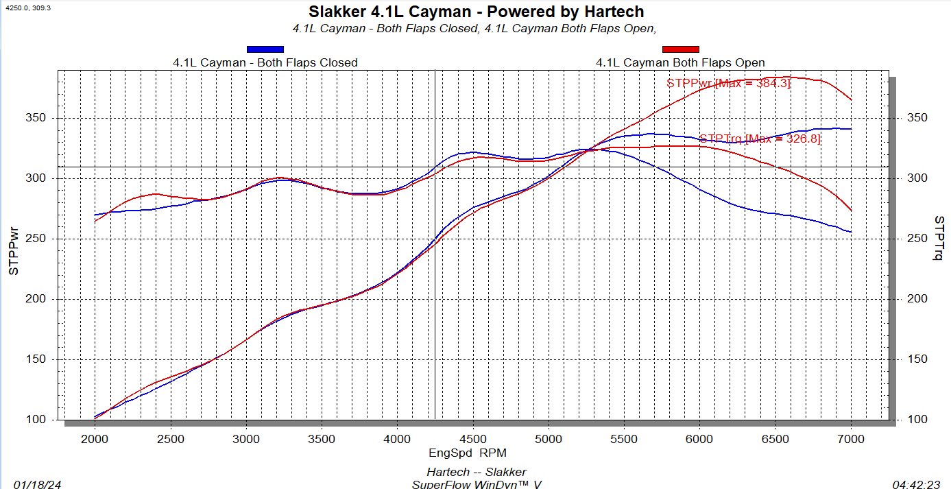
Bonus content- Here is a graph that I got from Brandon at Slakker Racing showing the positive effects of the butterfly valves in the intake tract, discussed earlier in this article.

Discussion
Comments are closed.