In my previous article, I discussed general assembly work in the area of the firewall and dash, while access was good. One item that is always a challenge is the installation of the wiper mechanism. Although ultimately I will not install the wiper spindles through the cowl until after the painting is done, I wanted to make sure the various parts could be assembled. I remember from doing this job on my 67 2+2 many years ago that access is poor. This time the first challenge was that I was missing some parts. That “car in a box” thing again.
The SPC calls it the Windscreen Wiper Link Set. There are 3 spindle assemblies that fit through the cowl to accept the wiper blades. I had the main link assembly but was missing the left and right spindles. I was only able to purchase a complete link set from SNG, which I guess was OK as it got me all new spindles. The left and right spindles are bolted to the main link assembly. As I was to find out, there is a reason for this. I don’t think there is any way in hell to get the complete assembly with 3 spindles inserted into the opening in the center of the dash. Even inserting just the main link assembly mounting bar is a very tight fit. Here are the various pieces laid out on the cowl. The long bar (about an inch wide) is the mouting bar for the main link assembly. It has studs at each end that engage the two holes you can see in the spindle brackets. The metal rods and the spiral cable are sold separately and are quite pricey in their own right so it is good if you don’t have to replace them.

Here is a picture of the link mounting bar being inserted into the opening in the center of the dash. It will only go in the direction shown i.e. towards the drivers side and it just barely fits. For this installation, I removed the center spindle, which includes the actuating rods, the park mechanism, and the spiral cable, saving it for installation in the next step of the process.


Once you get the link mounting bar into the opening, you carefully work it back to the passenger side until it is centered in the dash. I started with the left and right spindles pre-installed in the cowl but at some point removed them, as they seemed to be in the way. Once you get the link mounting bar inserted, you can insert the center spindle mechanism, insert it through its mounting hole in the center of the mounting bar, and then through its hole in the cowl. Loosely retain it with the external hardware. Next I inserted the left and right spindles through the small openings on both sides of the dash, inserting them through the cowl, and loosely assembled their hardware to hold them in place. Next I very carefully made up the studs and nuts. Put a towel in the “drop zone” because if you drop anything in there you will very challanged to retrieve it.
Speaking of parts to drop, as most of us know there are shiny chrome “bezels” on the outside of the cowl. These are cut at a severe angle to position the spindles in their inclined position. What I did not know is that there are corresponding bezels on the inside of the spindles. These did not come with the SNG rack and SNG did not offer them for sale. What I wound up doing was taking some of the chrome external bezels and modifying them to use inside. If you do this, you will see that you will need to use a grinder to cut a locating notch in them. Not a big deal. Anyway, these must be mounted on the spindles after you insert them through the mounting bar but before you insert them through the cowl and, yes, some of mine fell off. Fortunately they are big enough to retrieve, although I had to use the old stick with duct tape on the end to get them.
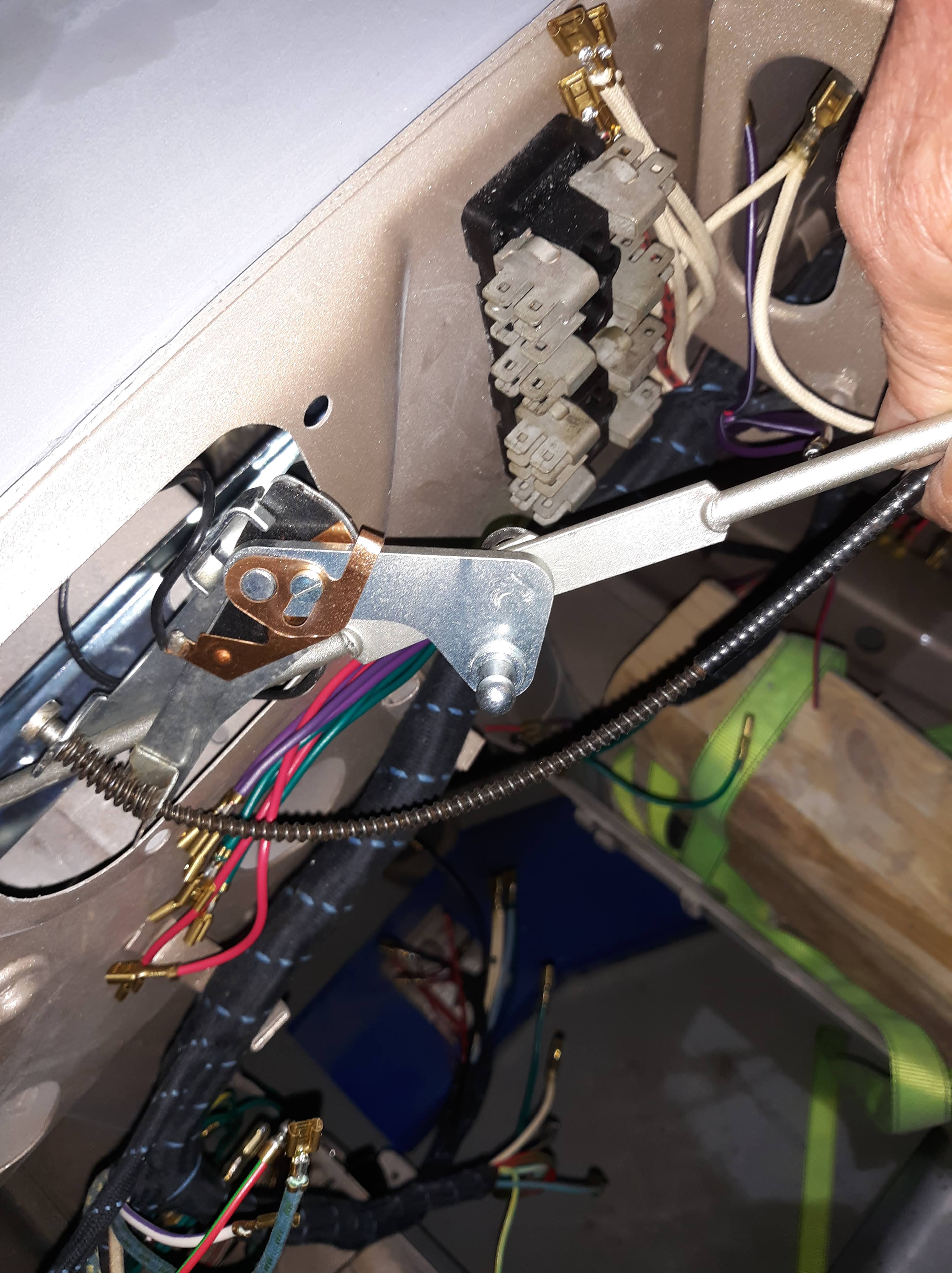
One caution. Apparantly the actuating levers for the drivers side spindle is slightly longer than that for the passenger side. Don’t get them mixed up.

Another thing that is tricky is the spiral cable. This cable leads from the main link to a knob. The knob inserts through the firewall and serves as the adjustment for the wiper park feature. You can rotate the knob and see how it adjusts the position of the park mechanism. Its exact function may not be obvious but trust me it works. You’ll just have to experiment with the insertion of this cable through its hole in the firewall but you want to get it into place early in the process because once the main link is in its final position, it’s too late to access the end of the cable. The proper hole in the firewall is unique in that it is recessed and inclined at a slight upward angle.


Once you get these pieces installed, you’ll have to attach the rods to the left and right spindles. You have to reach through even smaller holes to make up these connections. There are little clips on the end of the rods that accept the round balls on the ends of the spindle levers. I understand folks live in fear of these clips flying off, never to be seen again. I laid some towels below the work zone and did not have any mishaps.
At this point, the main parts are hooked up and you can articulate the pieces by hand to make sure they articulate freely and they don’t foul on anything. If this is a final assembly, you hopefully have already installed the squirter nozzles. Their hoses need to be kept neat so they don’t foul the wiper mechanism.
A slightly different story is the restoration of the wiper motor. I will keep that story short by saying I removed the cover on the gear case, removed all the old grease, put in new grease, put that back together, and painted everything in what my research told me was the correct colors. This was discussed in Part 1 of my firewall article here.
I was able to insert the motor, with its actuating rod, through the opening in the firewall. Again, the fit was very tight. I would hazard to guess that if the motor has stopped with the actuating lever at its worst case position, you would not be able to get it in. But mine did fit, barely. I tightened down the 4 nuts for the motor and test fit the rod.
Since I still needed to paint the cowl, I then disassembled all the hardware outside the cowl and carefully forced the 3 spindles down below the surface of the cowl. When I’m ready to reassemble it for the final time, I should be able to pop them back up into position, add the rubber pads, chrome bezels, and mounting nuts and be ready for the wiper arms, near the very end of my project!
Now do you understand the title for this post???

Discussion
Comments are closed.