In my most recent articles, I discussed painting the engine frames, picture frame, and bonnet frame. I also loosely assembled the bonnet. One might logically think the next step would be to assemble these items on the body shell. And certainly that would be one approach, especially if you had a deadline you were trying to meet to get the car to a painter or such. In my case, I am taking a slightly different approach. Anyone who has spent time squatting inside the cockpit of a FHC, working on dash wiring, knows that it is not the most comfortable work environment for an older gentleman. When I was a kid, I was the catcher on my Little League baseball team. I could comfortably squat for hours. No more. So I decided to do some installation work on the firewall and the dash. All these areas are painted and can be masked when the exterior paint is applied. The car body is sitting on my single post lift, at a comfortable working height. And with the engine frames yet to be installed, I have great access.
First I did an inventory of items I might be missing. I already had most of what I needed but my review resulted in a modest order from SNG. The most expensive item was perplexing. Whoever took apart the windscreen wiper mechanism had removed the 2 outer spindles. And they are now missing. Fortunately this mechanism is available from SNG. Unfortunately, I can’t buy just the spindles, I have to buy the whole thing. That is the way it goes when you are putting together someone else’s disassembled project. Most of the other missing items were modest in cost.
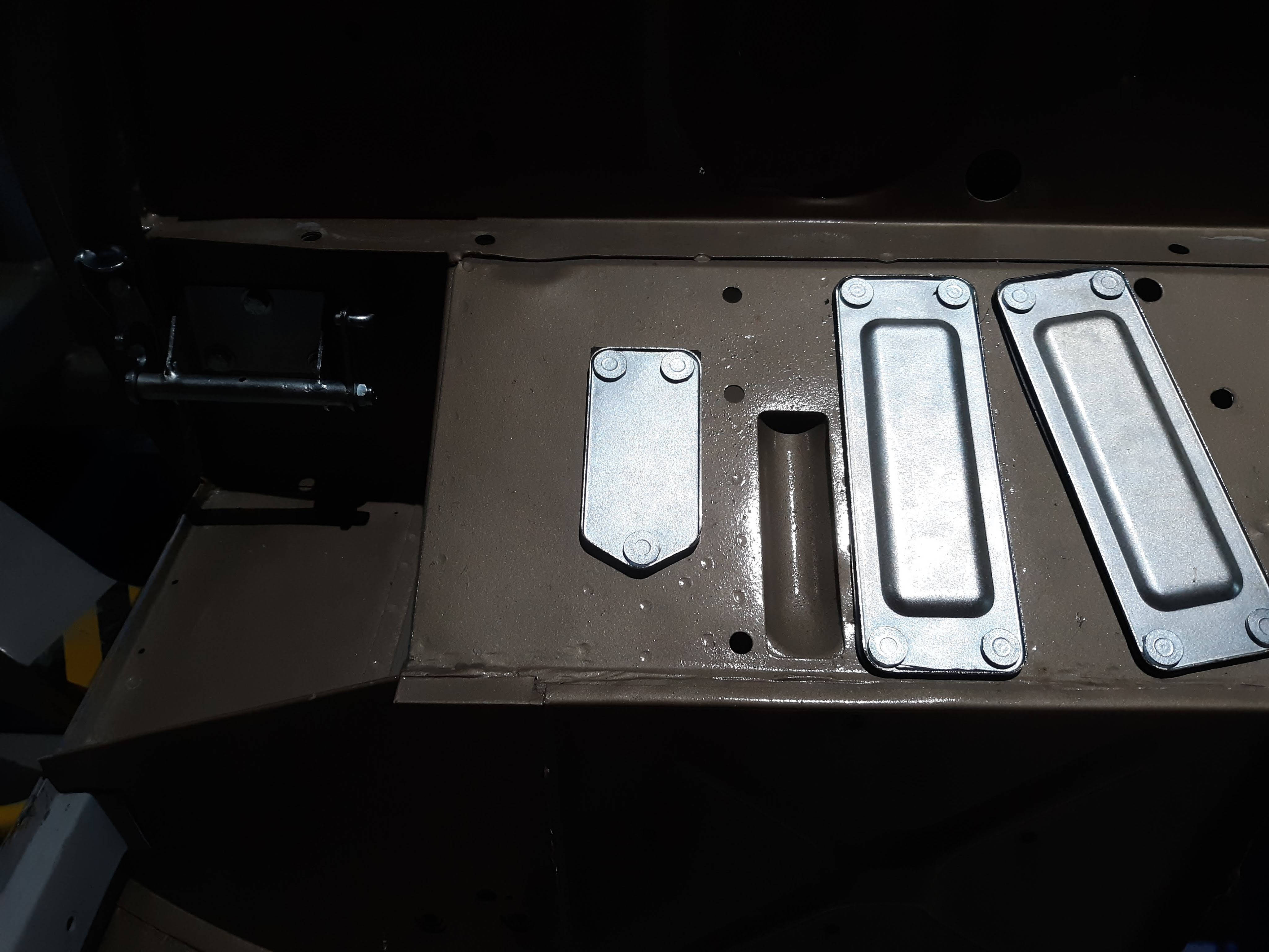
I reviewed the assembly sequence as recommended by others on Jag-Lovers. The consensus seems to be do the heater/vacuum tubes first, then the screen washer jets, then the wiper assembly. Since the scuttle remains to be painted, I’m only going to put in the tubes and the wiper motor for now. The tubes have a reputation as being a tough job but with wide open access, they were very straightforward. I pre-painted the little D shaped retaining plates black. The 3 rivets on each plate will get some black touch up paint later. 5 riveted connections are shown. The 6th is for the heater water line. It will get a rubber O-ring, a spacer plate, and the heater valve. The O-ring and the spacer plate will be installed when my parts order arrives. BTW, an overertly “clunky” rivet gun will not fit into the available space very well. The better quality rivet guns tend to be more slender.

There are other items to be installed that were recently received from the zinc platers, as discussed here. The cover plates for the throttle/brake/clutch housings on a RHD car were an easy installation. It has been reported that these may have been body color for “paint to sample” cars but generally they are silver cad. Don’t forget the rubber gaskets.
I decided to go ahead and work on the electrical harnesses that terminate in the center of the dash and feed into the engine compartment. First I found the 4 fuse blocks. I lightly dusted them in my beadblast cabinet. Then I sealed them with the product shown below, made by Honda.

This is a useful detailing product made for Honda to use on its motorcyles. It is part lubricant and part protective wax. I have used it before with good effect. And yes, I did a test to confirm that the product would not interfere with the electrical conductivity of the blade terminals on the fuse panel. My test meter said No Problem. Here are the fuse blocks mounted.

As a parallel path activity, I had been searching out items to be cleaned, detailed, and painted. One obvious item for the firewall was the wiper motor. Probably stupid to detail first, test later, but as we will see that worked out OK. The JCNA Authenticity guide has some things to say about the wiper motor. “Dark grey hammertone with an aluminum end plate”. The wiper motor I had exhibited aluminum end plates in good condition, a “pot metal” fixing at the bottom end, and in between a body casting that appeared to have been painted a long time ago in a black crinkle finish. I lightly bead blasted the aluminum pieces and sealed them with Eastwood Diamond Clear. After some false starts, I found a dark grey rattle can paint for the body. Even after bead blasting the crackle finish remained, so I decided that is how it was originally made. I just dusted it with the grey paint, to preserve the texture. It turned out pretty well, I think.

Swinging back around to Eastwood Diamond Clear, it is a product that I have had some success with. I typically use it to seal bead blasted aluminum. The label says it is good to 300 degF so it is probably not appropriate for parts directly on the engine like the valve covers. Be careful, it comes in 2 flavors. One is for direct to metal. The other is for application over paint. I have also used their Alumablast product, which does a good job of mimicking “as cast” aluminum.

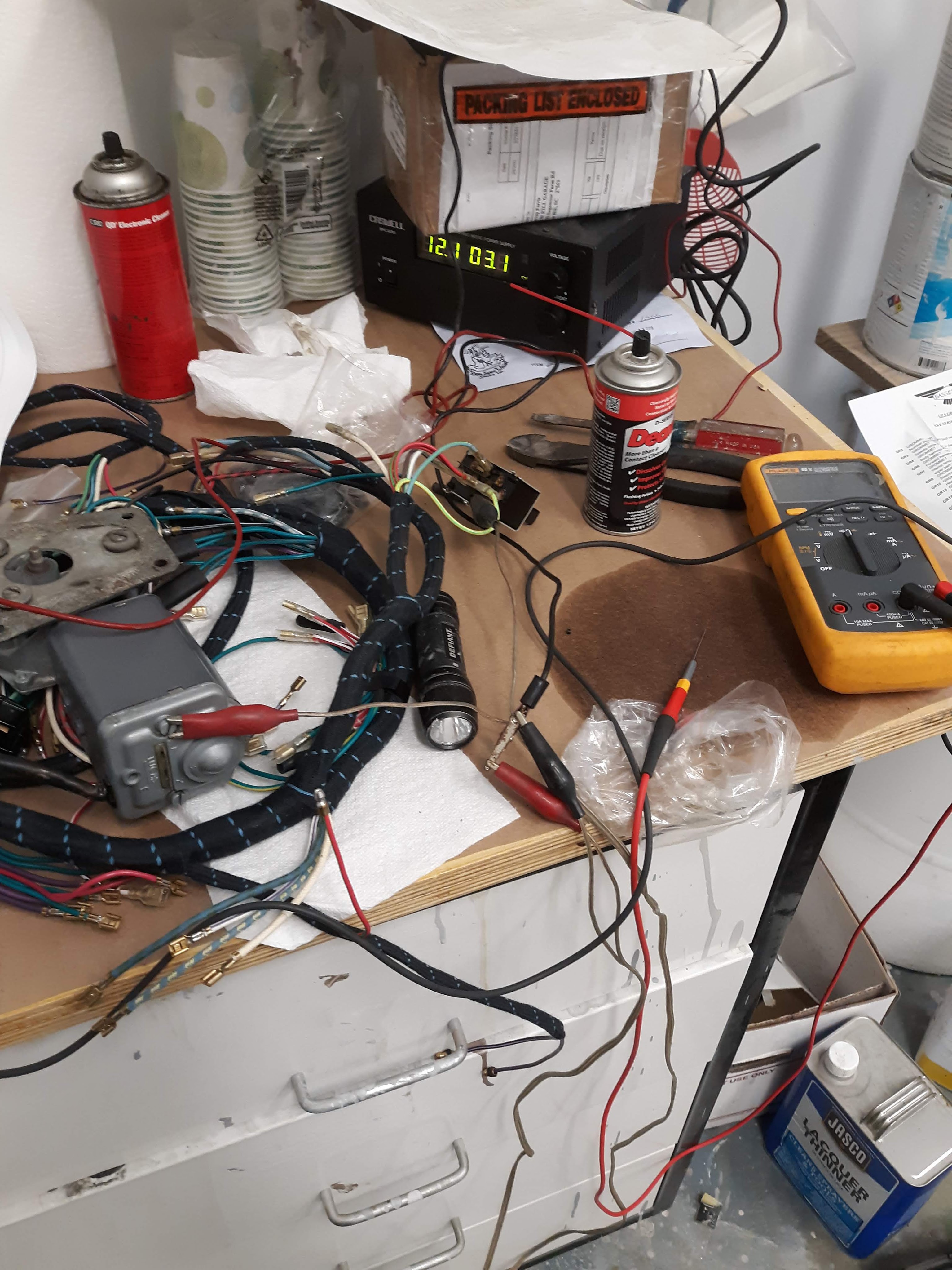
Now that I had the wiper motor all spiffed up, I decided to see if it actually worked. I removed the switch from the dash panel and extracted the applicable harness that I had purchased from Rhode Island Wiring (RIW). I was very lucky in that the wiring colors coming out of the wiper motor were still distinguishable. Unlike the motor on my 2+2, where the colors were all faded and I had to reconstruct the colors. But that’s another story. Anyway, between the wiring diagram in the Bentley manual and the wonderful wiring diagrams provided by RIW, I was able to hook up the assembly for a bench test. Power on. Switch on. Nothing. Darn. At this point I turned to an article I did years ago about the wiper motor. This article links to a pdf of a wonderful article by Dick Vandermeyden (rest-in-peace) that explains how this wonky motor is wired. Seriously, you will never figure it out on your own! Anyway, Dick’s article provides the continuity requirements for the switch. My swtich was not making the proper connections. I carefully removed the back of the switch and was able to spray Deoxit contact cleaner into the switch. After puting it back together the switch ohmed out correctly. But still the wiper would not work. I starting checking for voltage and found it to be missing. I had misunderstood the harness routing. Applying voltage directly to the motor lead, the motor sprang into life. Eureka!
That was a great feeling. Here is a picture of my test setup. Not meant to be instructional, just to impress you that there were no fires reported! So that’s it for now. The articles will come on a more regular basis as Some Assembly Required is going to be my mantra for the next few months.

Discussion
Comments are closed.