My Porsche 944 track car donated it’s engine block to my Porsche 944 “R”. That was OK because I had a replacement block waiting in the wings. This series of articles will document in some detail the building of a 2.5 litre normally aspirated 2 valves per cylinder Porsche 944 engine.
The starting point of the build was a block I purchased used that came out of a 951 (944 Turbo). The block had scored cylinder walls so I had steel sleeves installed by a local machine shop.

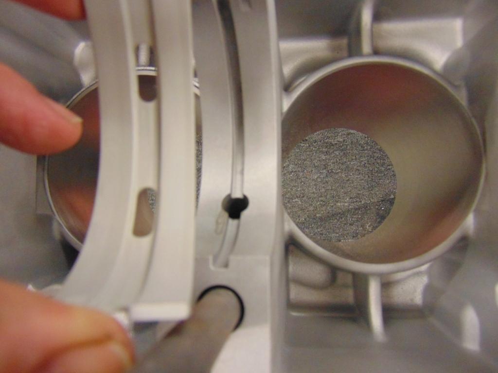
Closeup of cylinder with a steel sleeve. This picture also has a piston ring installed to check ring gap.
One thing I hope you will notice in this and the pictures that follow is the clean condition of the aluminum parts. Most machine shops will dip blocks, heads, etc. in a chemical bath to clean off grease and grime. But I have found that this doesn’t really get everything off. If it did, I would be worried that they left it in the bath so long that the aluminum might be attacked. My preference is to clean the parts in my blasting cabinet using glass beads. One downside is that you have to be vigilant to subsequently get out all of the blasting media from all the nooks and crannies. I use a combination of compressed air, water, and aerosol brake cleaner. For the block, I also remove the plugs at the ends of the oil gallery so that it gets cleaned out. For a better appearance, I spray paint all the outside surfaces with a “cast aluminum” spray paint. But do not get any paint on the interior surfaces, as it could come back off and wind up in the oil, with possible catastrophic results.


As we go through the process, having the Porsche shop manual will be vital. It has torque values and special tips regarding putting together your engine. I am fortunate to have an original manual in a 3 ring binder that I can flip the pages on but versions are available on CD for a modest price. Almost as important is the Porsche parts manual, the PET. It is available for free at the Porsche website. The exploded views it contains are invaluable and it will give important clues regarding the size of o-rings, oil seals, bolting hardware, etc.
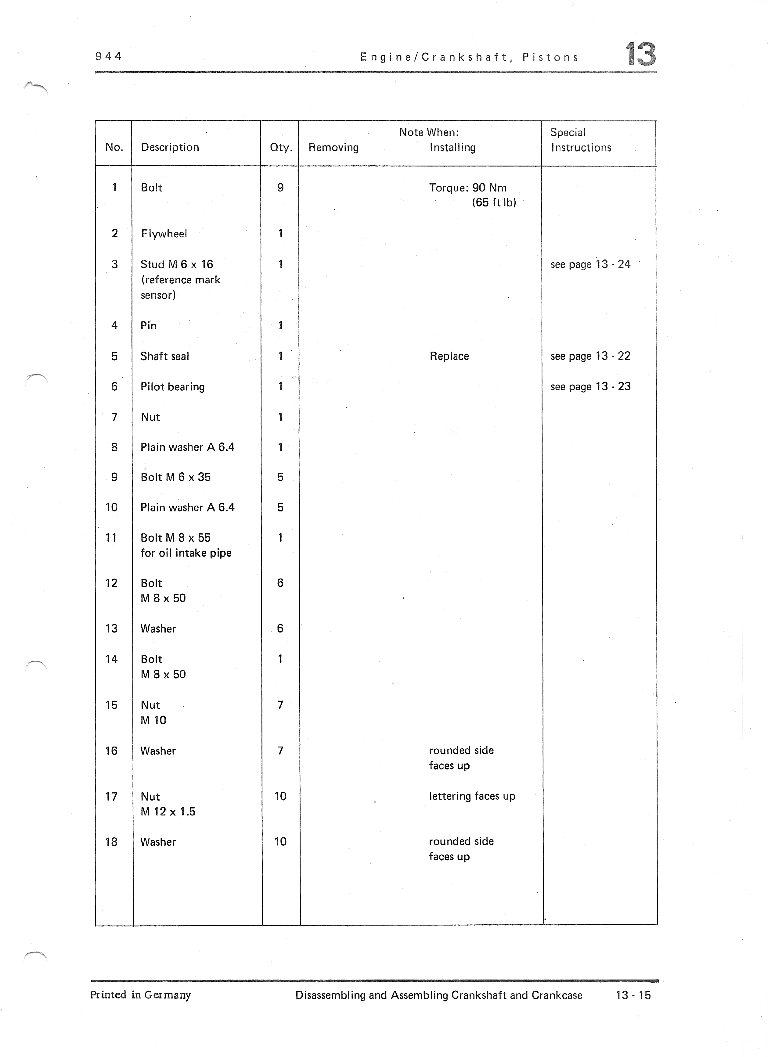
Pages in the shop manual like the ones shown below present helpful information. That said, this is not a step by step instruction. Rather it addresses all the key parts by number and provides tips or cross references to sections of the shop manual that pertain. The part numbers are the same as those used in the PET.

Another bit of info you will need is your engine number. In some cases, the part you need will depend on not just the model number and year of your car but on the actual number of the engine. It can be found on the drivers side rear of the block.

If you look at the back of the PET, the various engine numbers are decoded. It turned out that my block is out of a 1987 car.
Another important detail is confirming that your crankshaft girdle and balance shaft covers are correct. These items are matched to your block. They all have a common number and have to match.

ID number on the block and crankshaft girdle

ID number of the two balance shaft covers
We are ready to do the first step, which is to install the crankshaft with its bearings.

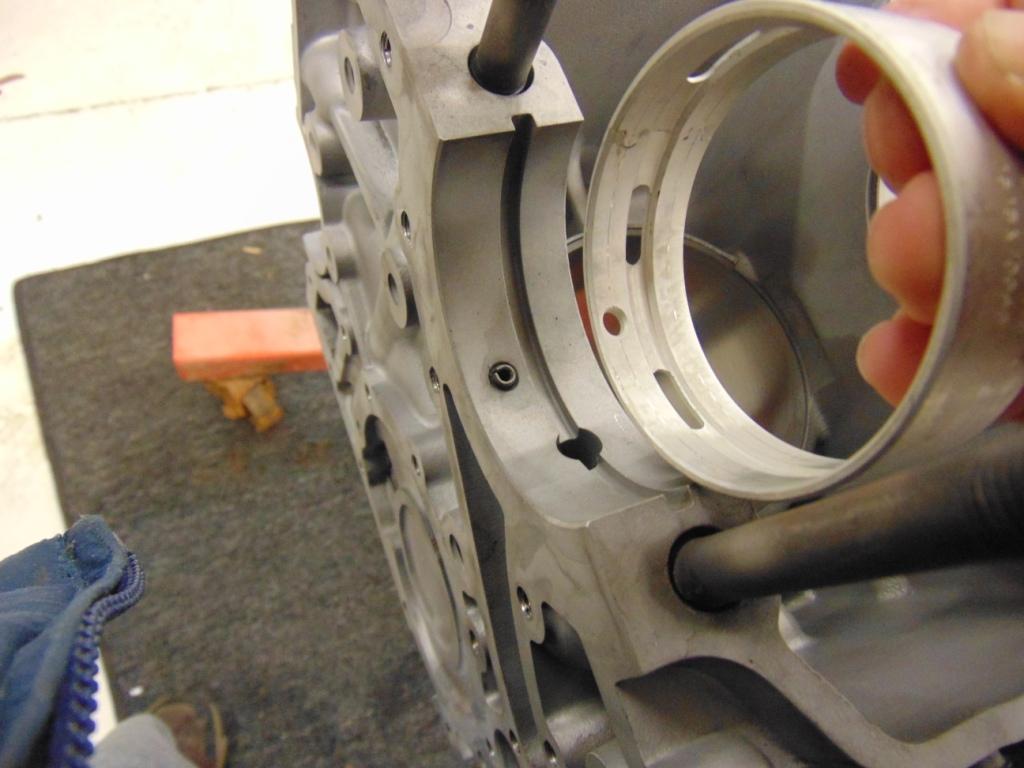
As you can see, most of the bearings consist of two half shells. The only real trick is to get the part with openings for the oil passages installed in the correct location.

Make sure the opening in the block for the oil is lined up with the opening in the bearing shell.
There are two ways to check the clearance between the journal on the crankshaft and the bearing shell. One way is to install the bearing without a crankshaft, torque the girdle hardware, and check the clearance with a bore dial gauge. This is what I did. You can also use Plastigage. We will look at using Plastigage in Part II.

Your bore gauge should come with instructions but in general, you check the OD of the crankshaft journal with a micrometer first. It should agree very closely (+/- 0.0005″) with the value given in the shop manual. You “zero” the bore gauge at this value. Then you insert the bore gauge into the round opening of each bearing location and determine how much larger than the crank journal the bearing opening is. The difference is your clearance. Acceptable values are also given in the shop manual. Except for really precise race engine builds, you are really just looking to confirm that the bearing shells were correctly manufactured, as the clearance is not adjustable.

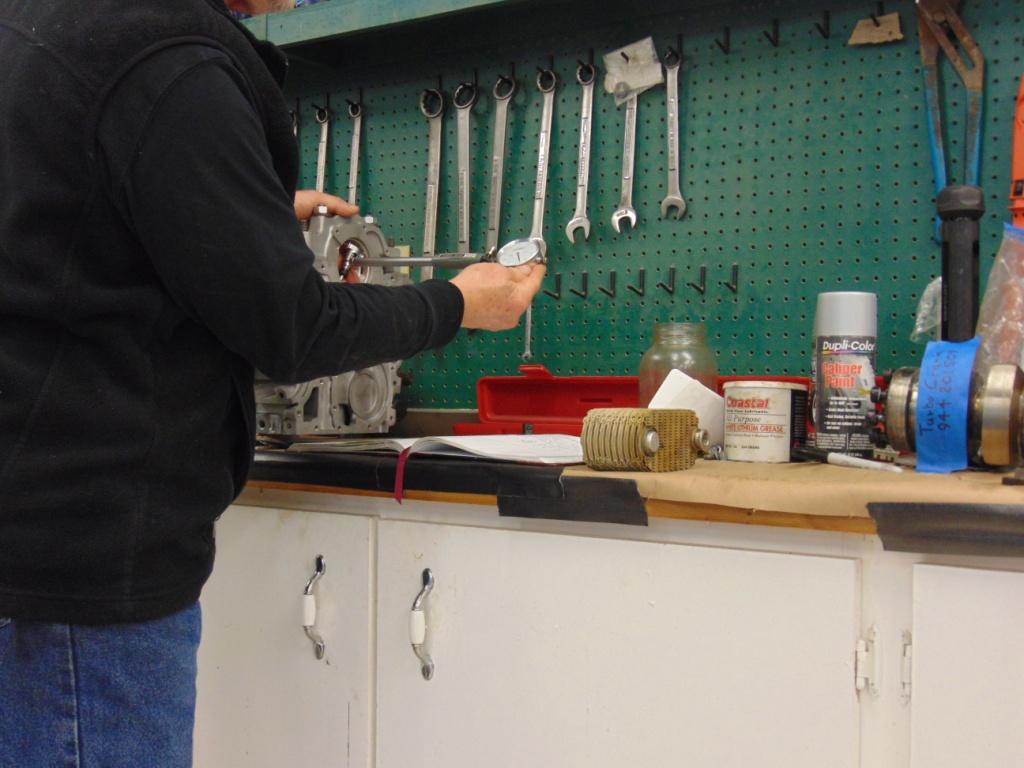
Checking the opening size at the outermost bearing.
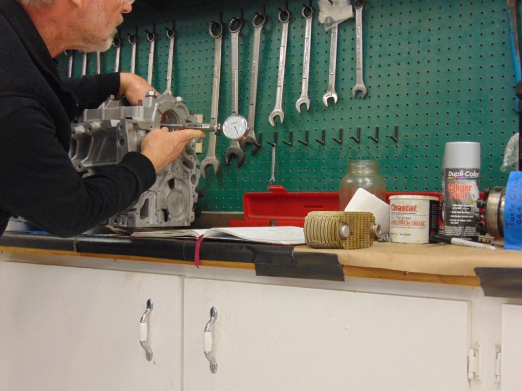
Checking the opening at an interior bearing.

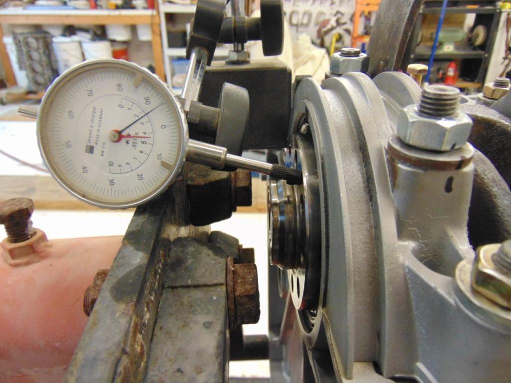
This bearing had a 0.004″ total oversize or a 0.002″ clearance between the crankshaft and the bearing shell
Once you think all the values are within tolerance, you will disassemble the crankshaft girdle and ready everything to install the crank. By the way, I took my crankshaft to the local machine shop. They confirmed that the journals were in good condition, measured them for diameter, and polished the journals.
The 944 engine has a critical oil passage that is captured between the block and the girdle. If it leaks, air may suck in, causing major problems.

Oil passageway from the oil pickup tube to the oil pump.
Also refer to my article Porsche 944 Oiling System Explained. The shop manual has explicit instructions on how to seal this passageway with Locktite 574. It is applied with a fine nap roller.


This Locktite is anerobic, i.e. it only cures in the absence of air. A little bit is all that is required, as the contact surface is precision machined.
Apply some Assembly Lube to the crankshaft journals, position the various bearings into position, and try to avoid back strain when you have to lift that very stout/heavy crankshaft into position! Assemble the girdle.
When you install the crankshaft girdle, there was a small check/adjustment important to installing the oil pump. After you put the crankshaft girdle into position but before you tighten its fasteners, you want to take your finger and feel the mating surface at the front of the girdle where it seats next to the block. The girdle can shift fore and aft a small amount. You want to shift it as required so that your finger does not feel any discontinuity or step at the mating surface. This is so when you come back later to install the oil pump, which laps over this surface, there is a smooth surface for the oil pump and its anerobic sealer to seal against. Specs for Locktite 574 say that it can seal gaps up to 0.25 mm. You can use that for guidance if you fit the oil pump and sense there is a gap. Feeler gauges should tell the story as to whether you have a problem or not.
Torque the various nuts to the values shown in the shop manual. Note that the largest M12 nuts are tightened by applying an initial small torque and then turning the nuts through a precise angle. The tool shown here, made by Lisle (P/N LIS28100), was very effective in keeping track of just how much of an angle had been applied.

As you snug things down, check that your crankshaft rotates freely. It should easily turn by hand. If not, something is wrong. Once you are done, you can check the crankshaft “end play” using a dial gauge. You will you use a small prybar to move the crank axially through its range of motion.
Checking crank axial play/clearance
That’s about it for the crank. The next article will move on to pistons, rods, and rod bearings.

The 944 crankshaft is a very beefy design, with main bearings on each side of the various rod bearings.
Following is a list of specialty tools that I used for Part 1:
Torque wrench: You must have torque wrenches to rebuild an engine. For this section, the biggest torque value you will be dealing with is 150 ft-lb. And there are a lot of small values in the 5 to 50 ft-lb range that will be applied, over and over. So you will really need a smaller wrench and a bigger one. I use a beam type for my smaller wrench and a clicker type for my big one. Do NOT buy from Harbor Freight. Take a look at http://www.mscdirect.com for some ideas on brands and pricing, then find the best price on the web.
Angle finder: The tool shown in the article. Not critical but for the $25 I paid for it, nice to have.
Micrometers: This is a tough one. Micrometers (unlike dial calipers) come in specific ranges. 0″ to 1″, 1″ to 2″, 2″ to 3″, 3″ to 4″. A piston is just under 4″. A crankshaft main bearing is just under 3″. A crankshaft rod bearing is just under 2″. And I use the 0″ to 1″ micrometer all the time around the shop. To do the entire engine rebuild, you may need the whole set, although your machinist can probably make the measurements you will need above 1″. Good micrometers are not cheap and cheap ones are not accurate. At a minimum, I would buy a good quality 0″ to 1″ micrometer and get a good quality 0″ to 6″ dial caliper. Do NOT buy from Harbor Freight. Take a look at http://www.mscdirect.com for some ideas on brands and pricing, then find the best price on the web.
Bore gauge: Definitely a luxury. Plastigage will suffice.
Calculator: I only mention this because every dimension in the shop manual is metric and you will be doing some conversions. That said, they give torque in newton-meters but give the equivalent ft-lb value in ( ).


I’ll admit it. I got very lucky and found most of these larger Starrett micrometers in thrift shops for a very good price. It doesn’t happen very often!

Discussion
Comments are closed.