In Engine Rebuild Part I, we looked at installing the crank in the engine. In Part II, we will look at installing the pistons and the rods.
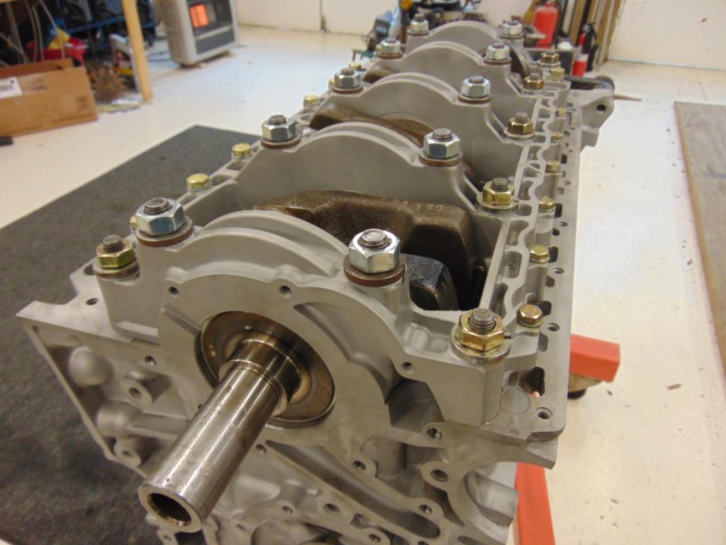
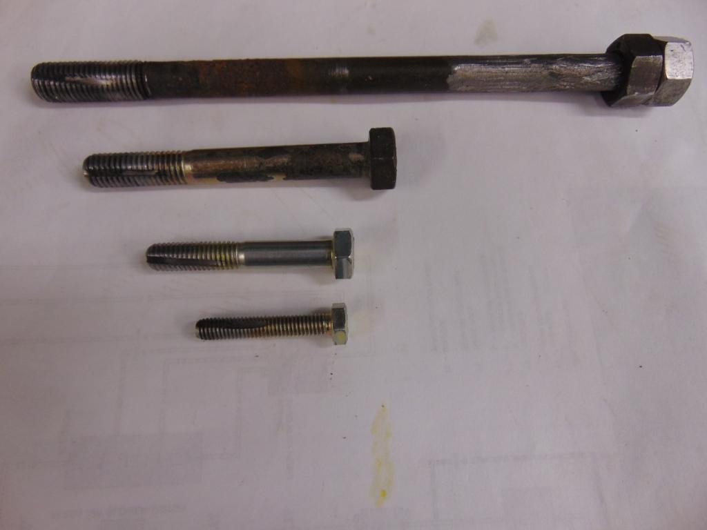
But first a word about prepping the block. As I noted in Part 1, I chose to clean the block in my blasting cabinet using glass beads. This allowed me to get the interior surfaces entirely clean. There is quite a bit of baked on oil residue in the interior of an engine and I felt it best to get it off. On the outside, I used the same approach but mainly for cosmetic purposes. As I noted, you have to be sure you get all the glass beads out. And it is safe to say, whatever approach you take, you will want to make sure you get the interior perfectly clean and free of any loose debris that could clog oil passageways or damage bearings. One other thing I recommend, while you have the block on the engine stand, is to clean out every tapped hole. If you don’t, you run the risk that whatever bolt or stud that goes into the tapped hole will not engage completely and/or any torque value you apply will be out of range because of the increased friction in the threads. For me, I clean the tapped holes with a combination of a thread chaser and brake clean. Similar solvents will also work. The tread chaser is simply a bolt or stud into which 1 or 2 grooves are cut into its length with a file or rotary cutting disk. The grooves give a place for the gunk to go as you gradually work the chaser in and out. Depending on how dirty the hole is, you may have to insert it a bit, remove it, spray the hole and the chaser with solvent, and repeat. I found that in particular the holes of the studs that attach the heads needed a lot of work. If you rotate the block on the engine stand so that the holes are facing downward, things go much better. Here is a picture of my thread chasers.
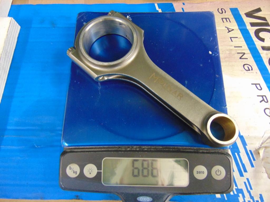
Although the original pistons and rods were perfectly serviceable, for this build I chose to go with new pistons and rods. There are 2 reasons. There is always a chance that the old parts may have hidden fatigue stress issues that will manifest themselves at the worst time i.e. at a track event. Also, for best power, new modern pistons, rings, and rods will provide the best performance. I decided to go with Wossner pistons and Molnar rods obtained from Racers Edge. Having steel liners in the aluminum bores, I had some concerns about what piston and ring product to use. After talking to Karl Potel at Racers Edge, he sent me in the direction of the Wossners. Just to be sure, I weighed the pistons and rods on a scale to make sure there were no significant differences in weight. I did not find any problems in this regard. The parts are beautiful!
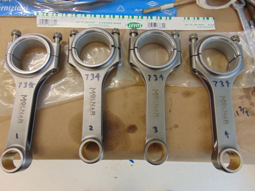
Although I don’t have a picture, the pistons come with piston pins that are used to attach the rod to the piston. The pins can be easily inserted by hand with minimal force. The pins are held in with circlips.
One of my first actions was to take the various rings (top, 2nd, oil) and fit them into the cylinder bore to check for “end gap”. Here is a picture. One checks the gap with feeler gauges.

Closeup of cylinder with a steel sleeve. This picture has a piston ring installed to check ring gap.
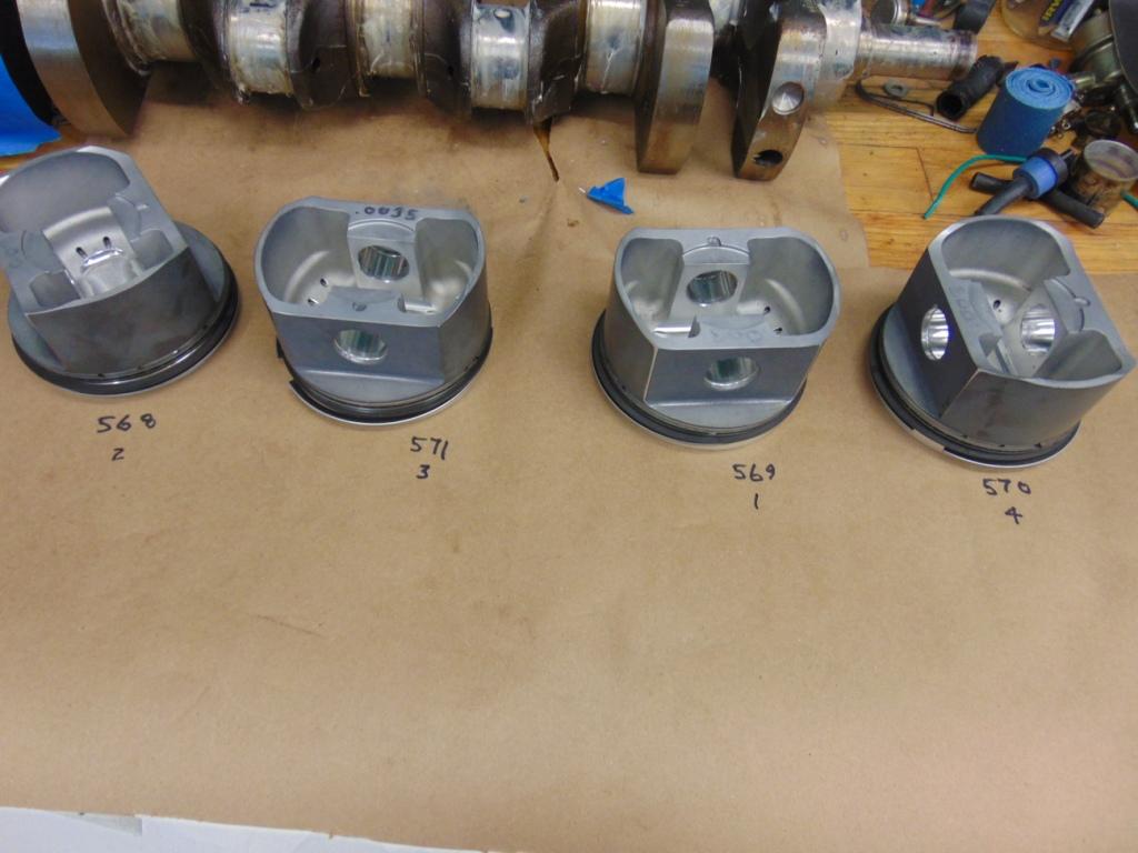
The end gap will close under certain thermal operating modes, so there is a minimum gap specified either in the shop manual or by the piston vendor. What I found was that the gap was wider than expected. It is not out of the question that rings could be manufactured incorrectly but in my case the problem was different. When I had the sleeves installed, I specified a finished bore diameter from specifications in the shop manual. For reasons I’m not completely sure of, the Wossners were set up for a slightly smaller bore. We’re not talking much here, the difference being 0.002″. But after talking to Karl, we agreed that the excess gap would cause excess “piston slap” when the engine was cold and was thus not desirable. Custom pistons to match my bore would be cost prohibitive. And I didn’t want to do the sleeves over either. So we decided to have the skirts of the pistons coated to build up the outside diameter (OD) of the pistons. For this I went to Swain Tech. They provide a service that applies a low friction coating to any metal object that has to slide. The nominal coating just to reduce friction is quite thin. But they also offer to apply the coating “heavy”. So the pistons were sent off to them for this job. When they came back, I used 600 grit sandpaper to polish the skirts back down to an OD that was the required amount less than the clearance required for the existing bore of the cylinders. Problem solved, I hope! One downside is that the ring gap still remains a little large so there is going to be some loss of compression there. So Lesson Learned. Have your pistons in hand before you make any final decisions about your cylinder bores.
Once the pistons were adjusted to fit the bores with the correct amount of clearance (BTW, Wossner recommends the clearance in the literature that comes with the pistons) it was time to install the rings. Again, you will want to check all your rings in their respective bores, just to identify any weird manufacturing errors. I use an inexpensive tool to expand and install the rings. You can do it without the tool although there is some risk you will snap a ring so be careful. Note that the ID numbers on the ring face up.
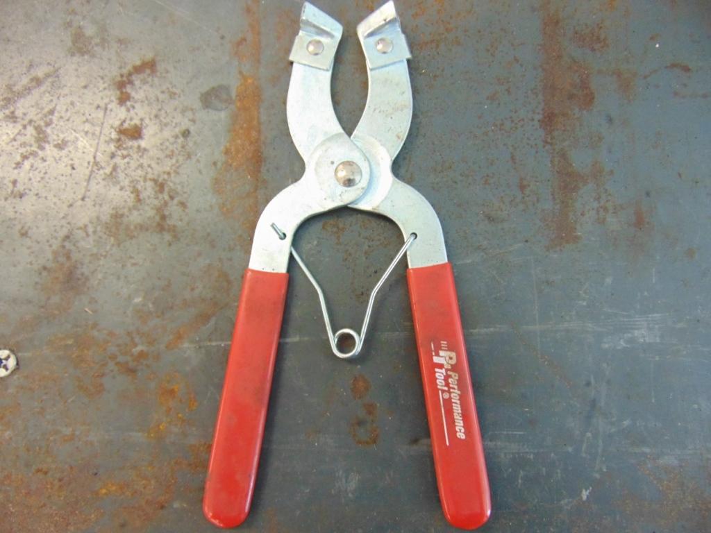
Tool for expanding the rings so they can me installed on the piston
Once the rings are installed on the pistons, it is time to install them into the bores. This requires a ring compressor and this tool is vital. I have done it in my hack mechanic days using just a hose clamp but I wouldn’t recommend it. The tool shown in the photo is much more elegant. Be careful, if you encounter significant resistance, back off and re-evaluate. I use a rubber hammer to tap the top of the piston. Tighten the clamp on the compressor dead tight, and then back off just a bit. Apply a coat of oil to the cylinder walls. Make sure the valve cutouts on the pistons are on the correct side!!!
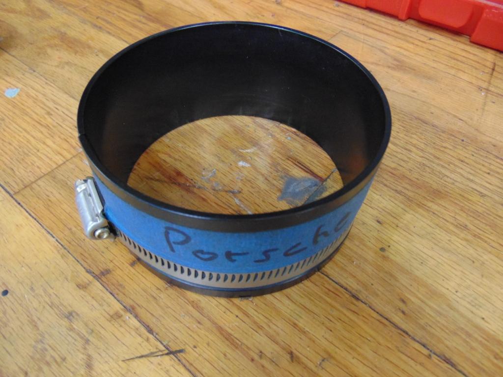
Piston ring compressor
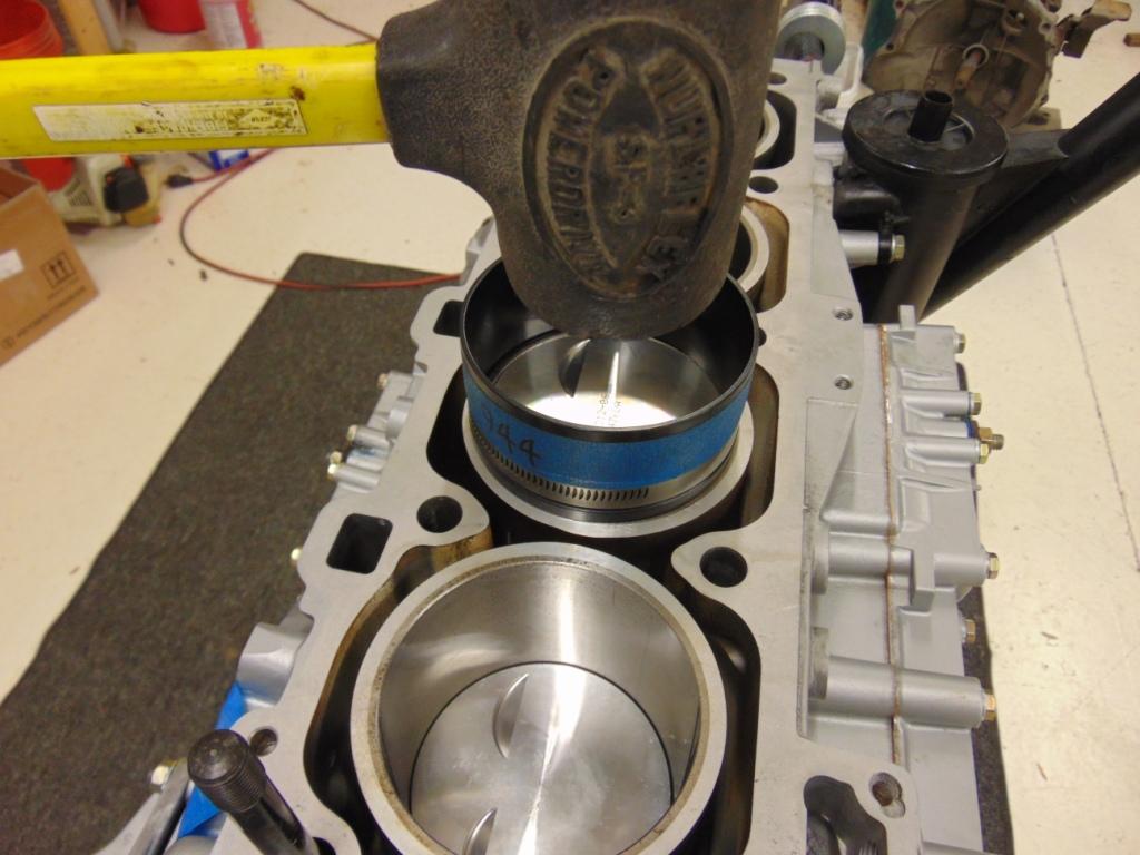
As you let the piston down into the bore, the other end of the rod will engage the crankshaft. It is probably best to do 2 pistons at a time with the opposing journals in the crankshaft at the bottom of the stroke. This will place it in the best position to install the rod bearings. You can actually pre-position one half of the bearing shell on the rod end. There is typically enough friction to hold them in. You should also pre-lubricate them with assembly lube. Also note that the shells have a “tang” on them. It should be obvious where the tang goes. If you can plan ahead, it never hurts to document how the tangs are located when you dis-assemble the engine. After the piston is carefully pushed down into the bore such that the rod engages the crankshaft, you can install the rod bearing cap. The Molners use special bolts to attach the caps. The stock rods use studs. The workshop manual recommends that new nuts be used and that you use their proprietary “Verbusrip” style of nut.
Once all the rods are attached to the crank, ensure that the crank still rotates freely.
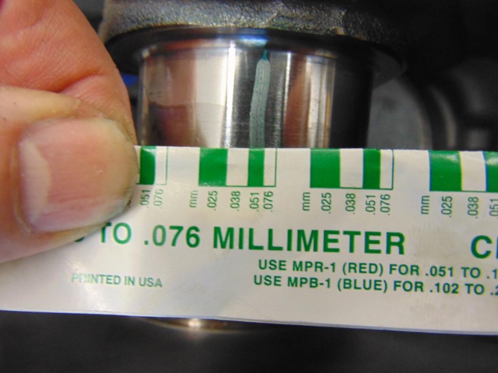
Now, we are ready to check the clearance on the rod bearings. In this case, I used Plastigage. Plastigage is an elegantly simple technique for checking clearances. It is basically a strip of plastic, formed to a precise, small diameter. You snip off a piece, lay it on the bearing journal, assembly the bearing cap, and apply a torque. You pre-select a diameter of Plastigage that is bigger than the anticipated bearing clearance. When the plastic is deformed by the bearing, it flattens out. How much it flattens out is indicative of the clearance. You compare your flattened piece to a guide printed directly on the packaging for the Plastigage and can get a fairly precise reading on the clearance. One side of the chart reads in inches. The other side in millimeters. Some tips: Clean the bearing surfaces where the Plastigage strip will be laid. Make sure your Plastigage strips are in good condition. Select the right size range. It comes in red, green, and blue depending on the gap to be measured. I used green for this job. You don’t need to apply full torque to the bearing caps. Just go to the first stage of torque, say 15 ft-lbs (the rest of the torque is used to stretch the bolts, it shouldn’t affect the clearance). You are mainly looking to see if your clearance is within the range shown in the shop manual. When you are done, you may want to re-apply assembly lube to the area you cleaned.
Now it is time to tension the rod cap hardware. With the stock nuts, follow the directions of the workshop manual. For the Molnar rods, they provide both a recommended torque and also a bolt “stretch”. Using the bolt stretch is the most precise. For this, I purchased a simple tool that mounts a dial gauge onto the bolt. As the bolt is stretched, you can read the amount on the dial gauge. Again, I feel this to be the most precise but the torque method has also never been a problem for me in previous 944 engine builds I have performed.
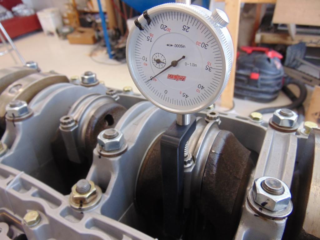
Special fixture that allows rod cap bolting hardware stretch to be measured. Note that I use a Sharpie marker on each nut as it is torqued, as a positive verification that the correct torque has been applied. On fasteners external to the engine, I use yellow nail polish, which is somewhat commensurate to what the factory used.
Don’t do what I did. When I had the rod attached, I rotated the crank and something didn’t feel right. A little investigation revealed one of the bearing shells lying on the floor under the engine! No real harm, since I noticed it. I cringe to think what would have happened if the engine got started this way. So be methodical and make sure that everything feels right as you work your way through the assembly process.
In our next installment, we’ll look at the installation of the cylinder head on the block.
Special tools required for this job.
Ring compressor
Plastigage
Torque wrench
Ring expander
Scale

Discussion
Comments are closed.