Based on a recent thread on Rennlist, I was prompted to check the camber values for a Porsche 944 rear suspension. In effect, I was looking at how the camber changes as the suspension goes through compression and droop. I previously did an article along the same lines for the front suspension here.
The rear suspension is a semi-trailing arm setup. This picture shows it pretty well.
 The blue tape in the foreground is attached to the end of the torsion bar, which is partially removed such that you can see its splines. The aluminum casting is the carrier, which bolts to the car. The “trailing arm” is formed as a triangle. The wheel/hub can move up and down but not fore/aft or side to side. Not shown is the “half shaft” that goes from the hub to the transaxle but it can be seen in the photo below with the suspension installed.

The question posed on Rennlist was generally of the nature of “Does this setup control camber very well during cornering?” Below is some experimental data that I took which provides some insight.
I removed the right rear wheel on my 84 street/track car, with the car on a low rise scissor lift. With the hub in full droop, I put a floor jack under the lower shock connection and jacked the hub upward until it was just coming off the lift i.e. the weight of the car on that side was just balanced by the torsion bar. In this position, the half shaft was running “uphill” from the transaxle to the hub i.e. the shock was compressed as if the wheel was under a cornering load. This would be the suspension in the compressed condition. I measured the slope of the half shaft, where a negative value means the half shaft is sloping upward from the transaxle to the hub. I then measured the camber at the hub. A negative value means the top of the wheel is tipped inward toward the center of the car. FYI most race tires provide their best grip with some amount of negative camber. The sweet spot can be as much a 5 degrees for certain tires.
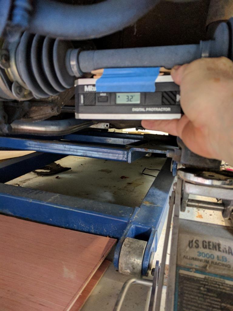
Slope of the half shaft being measured.

Camber at the hub being measured.
I gradually lowered the jack and measured the 2 locations for each step. Here are the values I obtained.
Half Shaft Angle / Camber at Hub
- -4.8 -3.0
- -4.0 -3.0
- -3.0 -2.8
- -2.2 -2.6
- -1.2 -2.3
- -0.4 -2.1
- 0.0 -2.0
- 0.7 -1.9
- 1.9 -1.6
- 2.7 -1.3
- 3.7 -1.1
- 5.2 -0.9
Note that since this car is set up for the track, the camber with half shaft level (0.0 degrees) is -2.0 degrees. For a street setup the value would be closer to 0.0.
It’s not an exact apples to apples comparison but in general the slope of the half shaft is a surrogate for the car body rotating during cornering loads. So you can see the camber change is a small percentage of the half shaft slope. The camber change for -2.2 degrees of half shaft slope is 0.6 degrees. The camber change for +1.9 degrees of half shaft slope is 0.4 degrees. To my eyes, these are pretty decent numbers.

Discussion
Comments are closed.