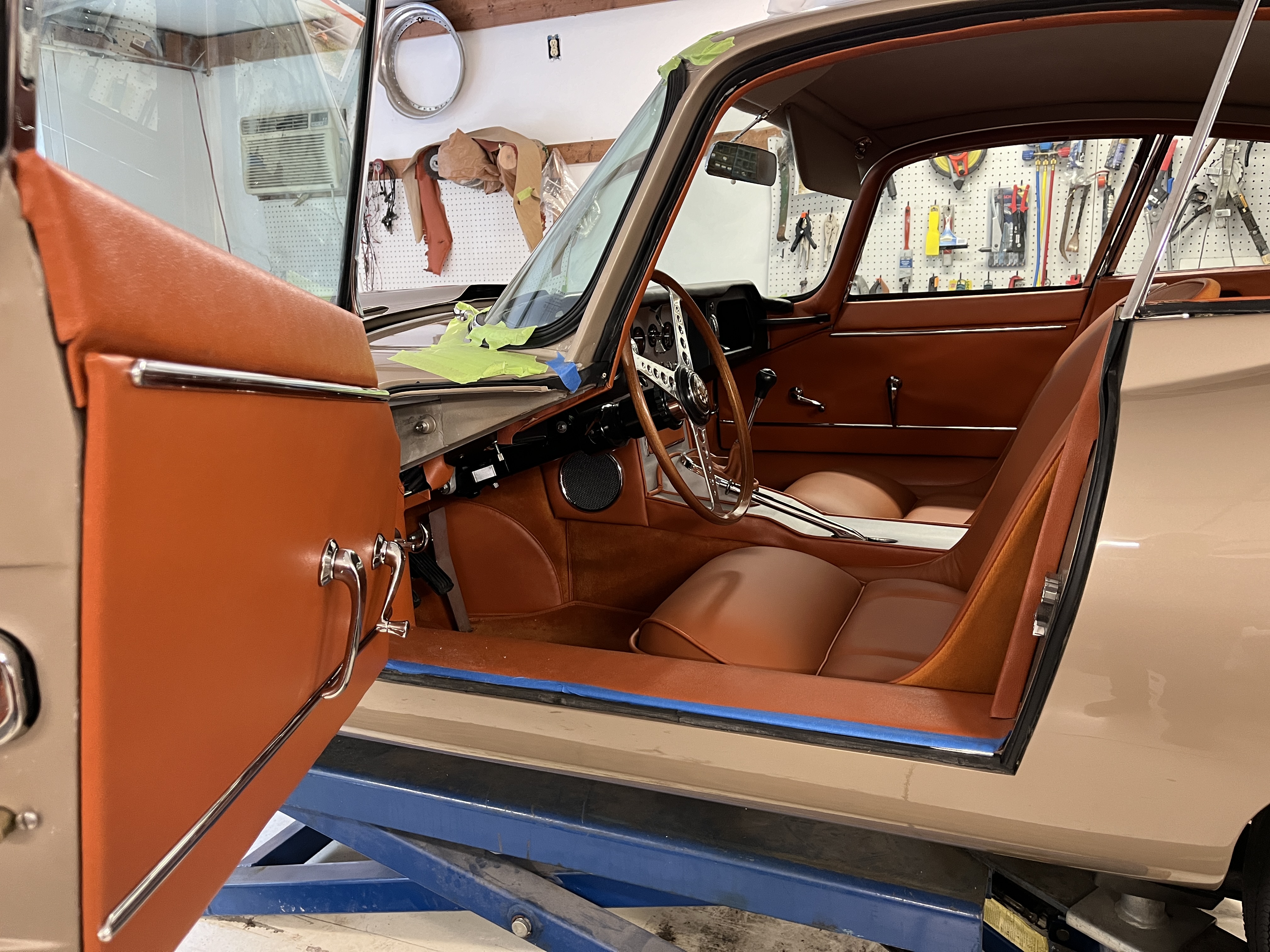
One of my recent tasks was to assemble all the parts in a bare door to obtain a completed assembly. There turned out to be quite a learning curve for this process. As such, I am going to do one of my deep dives with lots of explanation and pictures. Note, if you come across this article wanting to know how to take your door apart, this article should be helpful. Actually, I’ll approach this from a standpoint of taking the door apart, since this is where most of you will be starting from. And be aware, my info is based on a car built in early 1963. Some details changed with the later cars.
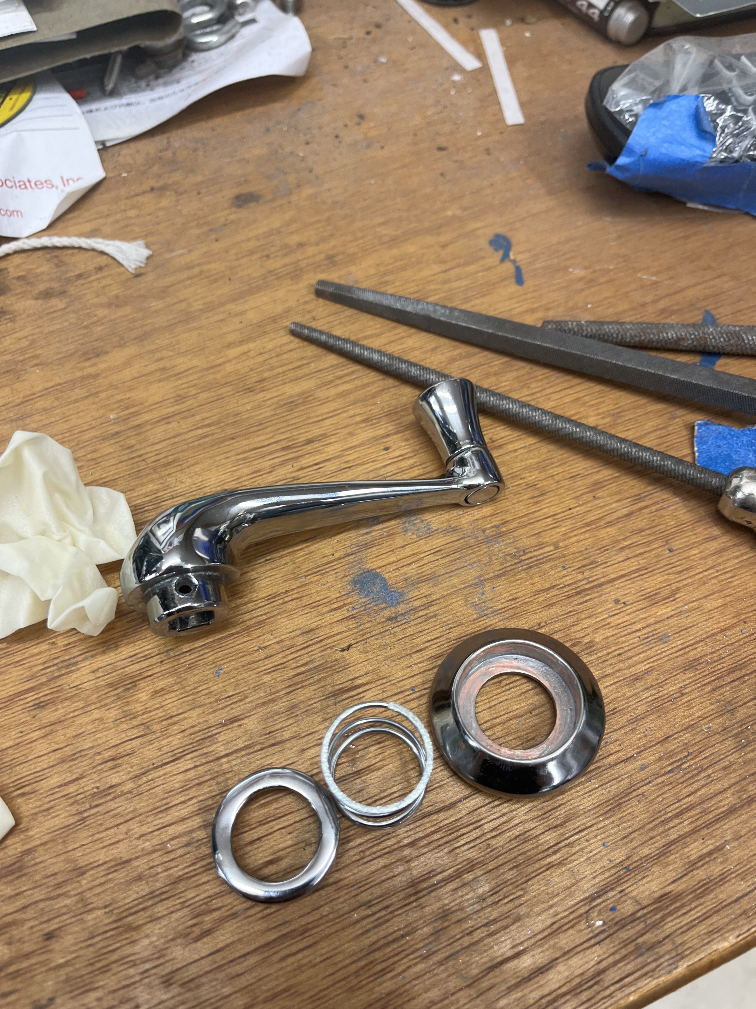
HANDLES- The first thing you will need to do is remove the handles. The handles are held in with short pins. If you push the “bezel” up against the door card, you should be able to expose these pins. You push them out with a small tool such as a punch or screwdriver. Hopefully your pins are not corroded or stuck. Once the pin falls out, the handle, two parts of the bezel, and a spring come right off. Also, my car was one of the last ones to not have an arm rest, which is sort of a handle. As I recall on my 67 2+2, the arm rest was attached with two screws visible if you crouched down and looked at the lower part of the handle.
Note that by the time the Series 2 cars were built, the handles were attached with an obvious Phillips head screw. Much easier!
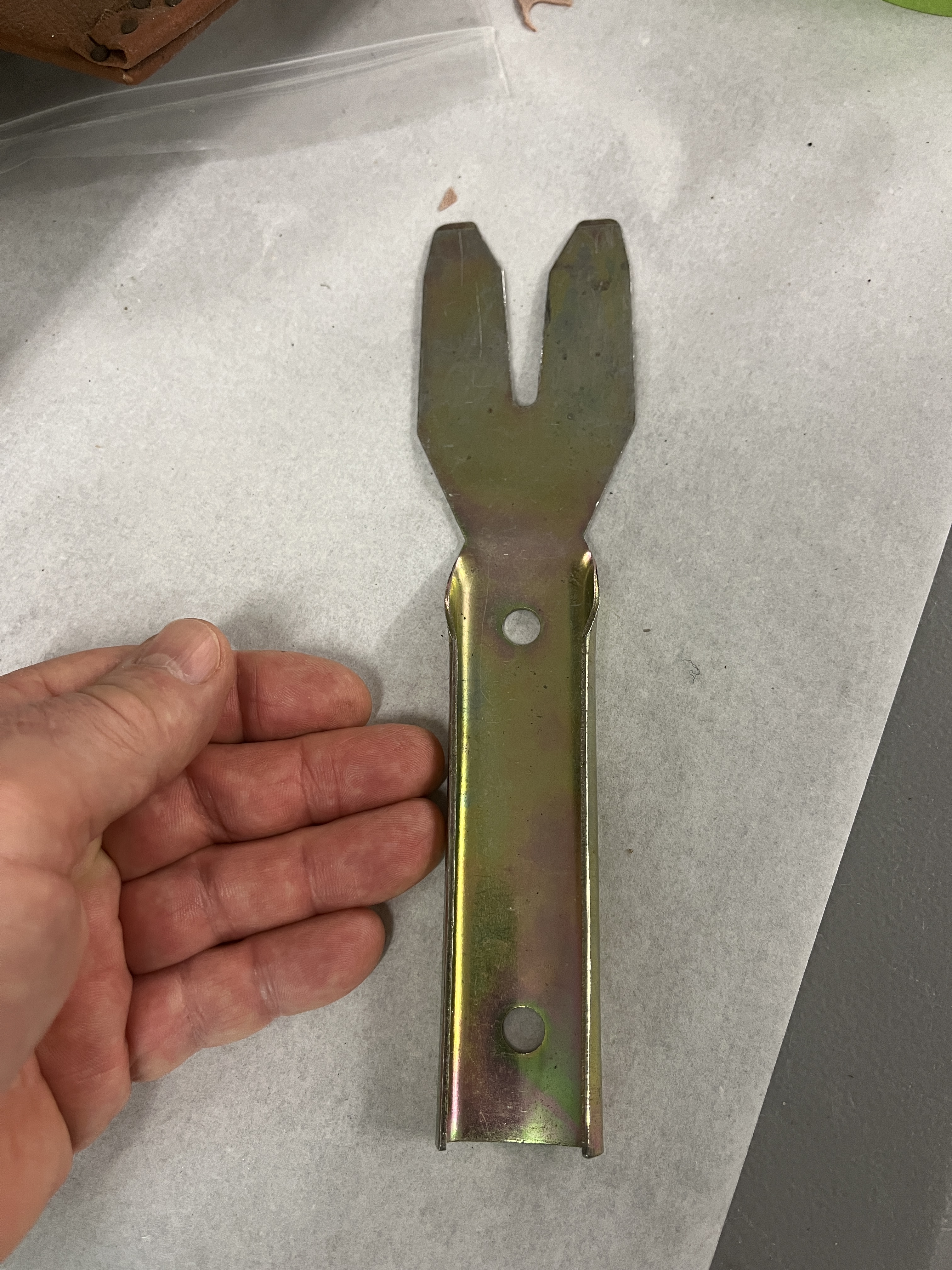
DOOR CARDS- Next you take off the door card. Here is where it may get tricky. The cards in general are attached around their perimeter with clips that engage into holes in the metal body of the door. Below in the photo section there is a picture of a special tool I use to pry away the door cards. But a screwdriver can work in a pinch. The clips are spaced every 3 or 4 inches. Depending on the year your car was built, there may or may not be clips across the top edge of the card. See more discussion below.
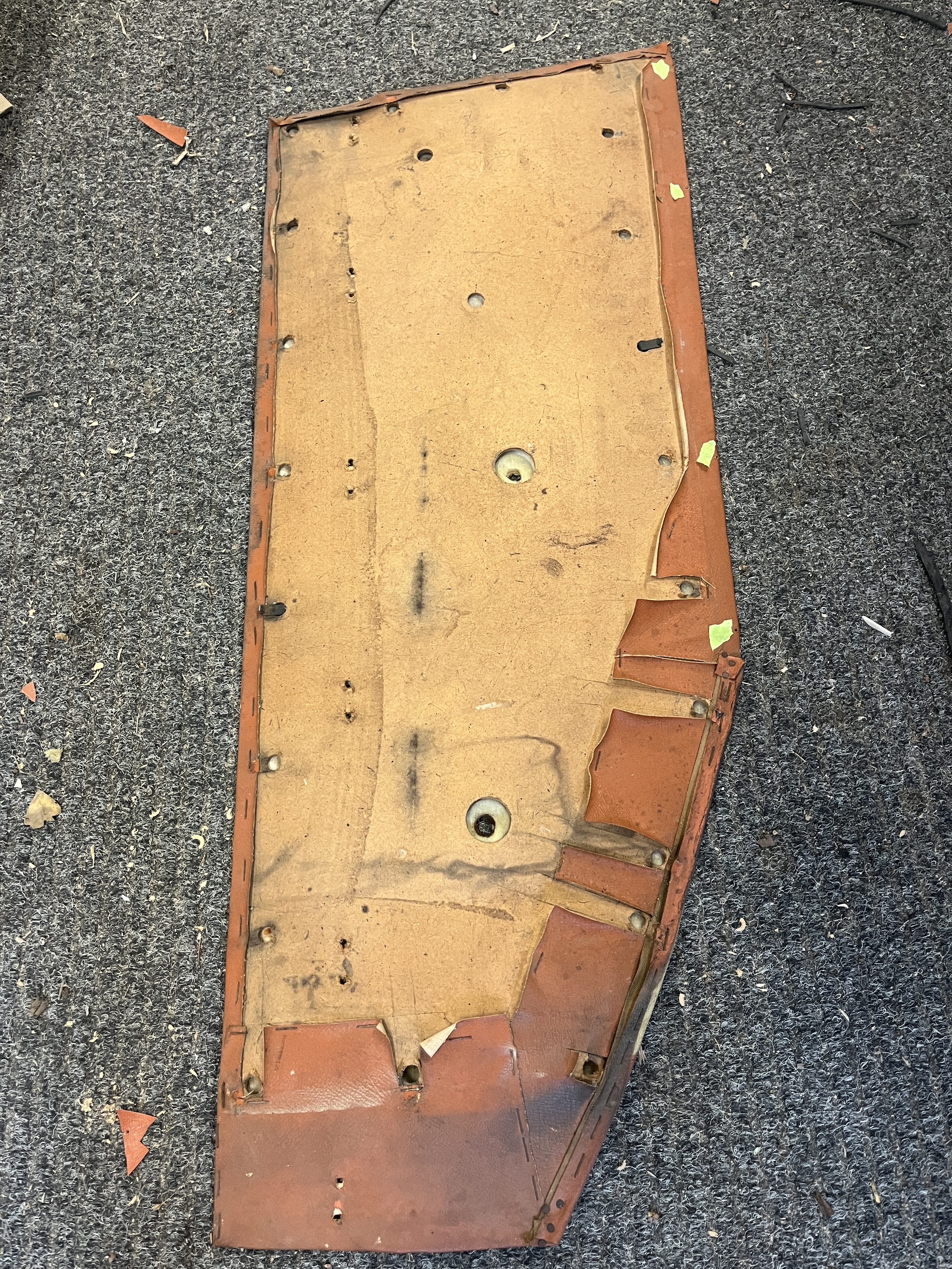
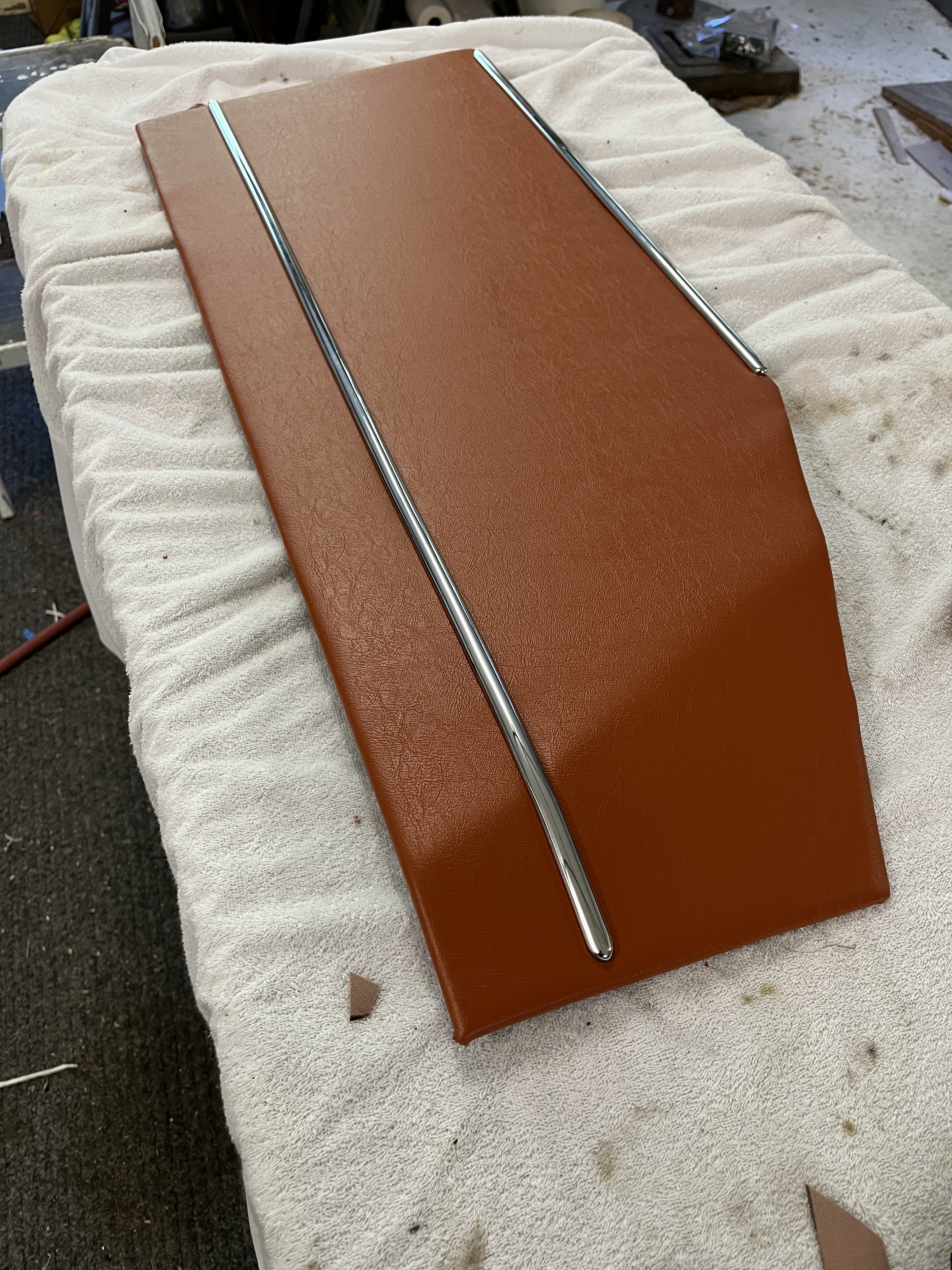
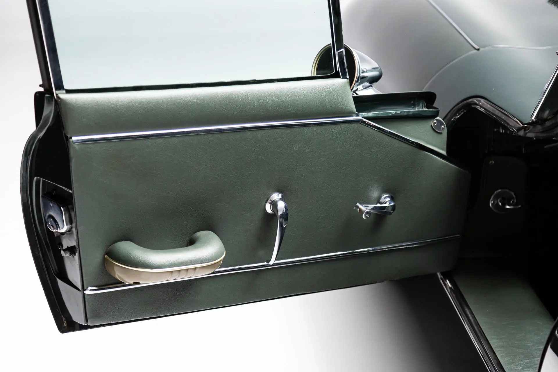
Problems and pitfalls- sometimes the clips just stay in the metal door and they rip out of the fibreboard paper door cards. If this only happens to a few of them, you can probably just leave the bad ones out going back. You might be able to locally repair the holes with a thin sheet of metal, punched with a hole and glued over the damaged hole. Or you may make a new door card. But that is another project. Another potential problem is with the chrome trim across the top of the door card. For early cars, it is as shown in my car, a rounded bar with pointed ends. The OEM factory installation has this piece attached with rectangular clips that are screwed into the top edge of the door card with sheet metal screws (and possibly into the door cap and maybe into the body of the door itself). In theory, you pry the trim off the clips. But after 60 years, yours may be modified. Note that there are spaces at both ends of the trim that are wide enough to pass the clip through. So there is a removal technique where you slide the trim forward to one end to release the first clip through the wide spot. Then you slide it the other way, releasing each clip as it comes to the wide spot. Unfortunately, there is a lot of friction, especially if some corrosion has occurred. I have not been in a position to try this method with original clips (my car came to me dis-assembled). I made a mod that allowed my new strip from SNG to be attached by sliding. At some point, the factory used a special pop rivet with a cup head. BD26706/1. This apparently did require that you slide the trim piece onto the cup heads, one at a time. Sometime late in the production of 3.8 cars, the trim was revised. It is an inverted J shape. The top of the door card slips up and under the J. This J piece is on the horizontal section as well as on the forward inclined section. I think you will find this piece is also screwed into the door cap and maybe into the body of the door itself.
DOOR CAP- Speaking of the door cap, it is typically going to have a few screws along its lower hidden edge that attach it to the door. Once the screws are removed, lift the rear end vertically a slight amount and then slide it rearward to release it at its front end. The door cap contains a felt strip which bears upon the glass. I ordered new ones from SNG. It was held on with clips.
OUTER GLASS WIPE- This is basically a squeegee that seals against the glass and wipes the water off as you lower the window. After 60 years, it may need replacement. Be prepared for different types and be prepared that you can’t really buy the original type that you may find on your car. On mine, I had to drill holes in the squeegee strip and the inner sheet metal of the door, to allow attachment with pop rivets. Since my door didn’t have holes, I am sure the original wasn’t attached this way but the use of pop rivets was required based on the replacement sent to me by SNG.
EXTERIOR DOOR HANDLE- You may be trying to resolve a problem with your door handles and latches. There are 3 basic components that work as a system. The “latch” is mounted on the shut face of the door. The nice chromed part extends through an opening and is held in place with 4 or 5 screws. The “exterior door handle” is of course mounted on the exterior of the door. It is held in place with two studs that stick through holes in the door skin and are retained with nuts. The removal of the “interior door handle” was discussed above but there is a actuator mechanism that protrudes through the inner door skin. It is held in with 3 screws. In all cases, you need to start by raising your window to be fully closed. This will get the glass out of your way. The mechanism that raises the glass will still be in there but in general, you can work around it. I don’t think you have to remove the interior door handle mechanism but you do have to disconnect the long flat rod where it attaches to the latch. There should be a small clip that fits over a small round with a circular groove in it. Generally, it can be removed with needle nose pliers. Personally, I have started using safety wire in the groove but whatever you find, you’ll have to remove it and slip the rod off the latch. On the far side of the latch (working from inside the car), there is a short vertical round rod that goes straight up to the outer handle. This also uses clips. They are harder to reach but small hands, a good light, and needle nose pliers should allow you to get one end of the rod. BTW, the chrome frame that the window nests in will be in your way but I do not think you need to remove it. Once you get the two rods disconnected from the latch, you can remove the outer screws and then snake the latch out. I recall that it works better to go around the front side of the chrome frame but you will work it out. Next, you can remove the two nuts and remove the outer latch. If you wish, you can remove the 3 screws that hold the inner latch mechanism and take it out.
A comment on the outer door handle. It’s mechanism is a little wonky. On mine, pushing the outer “thumb button” extends a smallish bolt on the inside. The bolt is adjustable, with a locknut, so you can mess with the engagement if you need to. Where is gets interesting is when you lock the outer handle with your key. After rotating the key in the lock direction, pushing the outer thumb button still happens but the bolt on the inside does not move. If this is not happening (which may be why you are taking out the handle!), look at the condition of the sheet metal cap on the inside where the bolt comes out. This cap historically breaks. There are also some “pot metal” pieces on the inside that snap off. Mine had both problems. I bought new handles from SNG. They are very reasonably priced, considering the parts count that makes up a functioning handle.
Another comment- the short rod that goes from the inside of the handle to the latch, as far as I can tell, serves to lock the car from the inside. Because it is hard to re-assemble, I left mine out on my build.
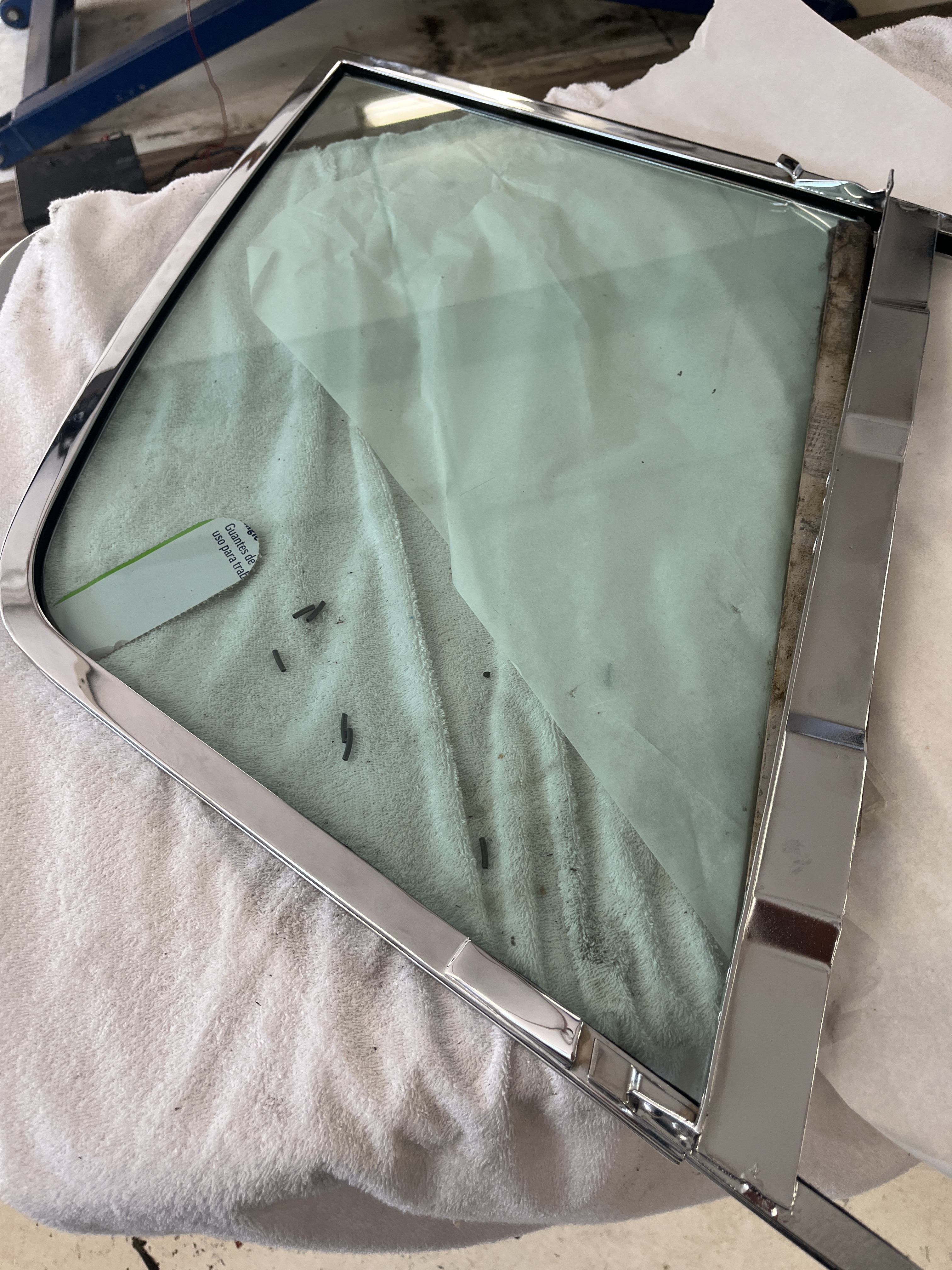
WINDOW GLASS AND FRAME- OK, this is where it gets interesting. For various reasons, you may want to remove the window glass frame and the glass. The sequence is different for the coupe versus the OTS. On both, the “cap” on the door must be removed. At the bottom of the glass, there is a horizontal metal track that is held onto the glass with mastic. This track accepts two rollers on the top of the window regulator mechanism. The regulator mechanism is a parallelogram. As it goes up and down the two rollers move horizontally in the track. To disengage the rollers from the track, you need to raise the window fully vertical and then go another inch or so. When you do this, the rollers will pop out of the end of the track and release themselves. On the OTS, although I haven’t done it, the shop manual says just roll the window up, get the rollers to release, and remove the glass. On the FHC, you first have to release the chrome frame. Once you release it, you pull it up at least an inch, which allows the glass to extend high enough to release from the rollers.
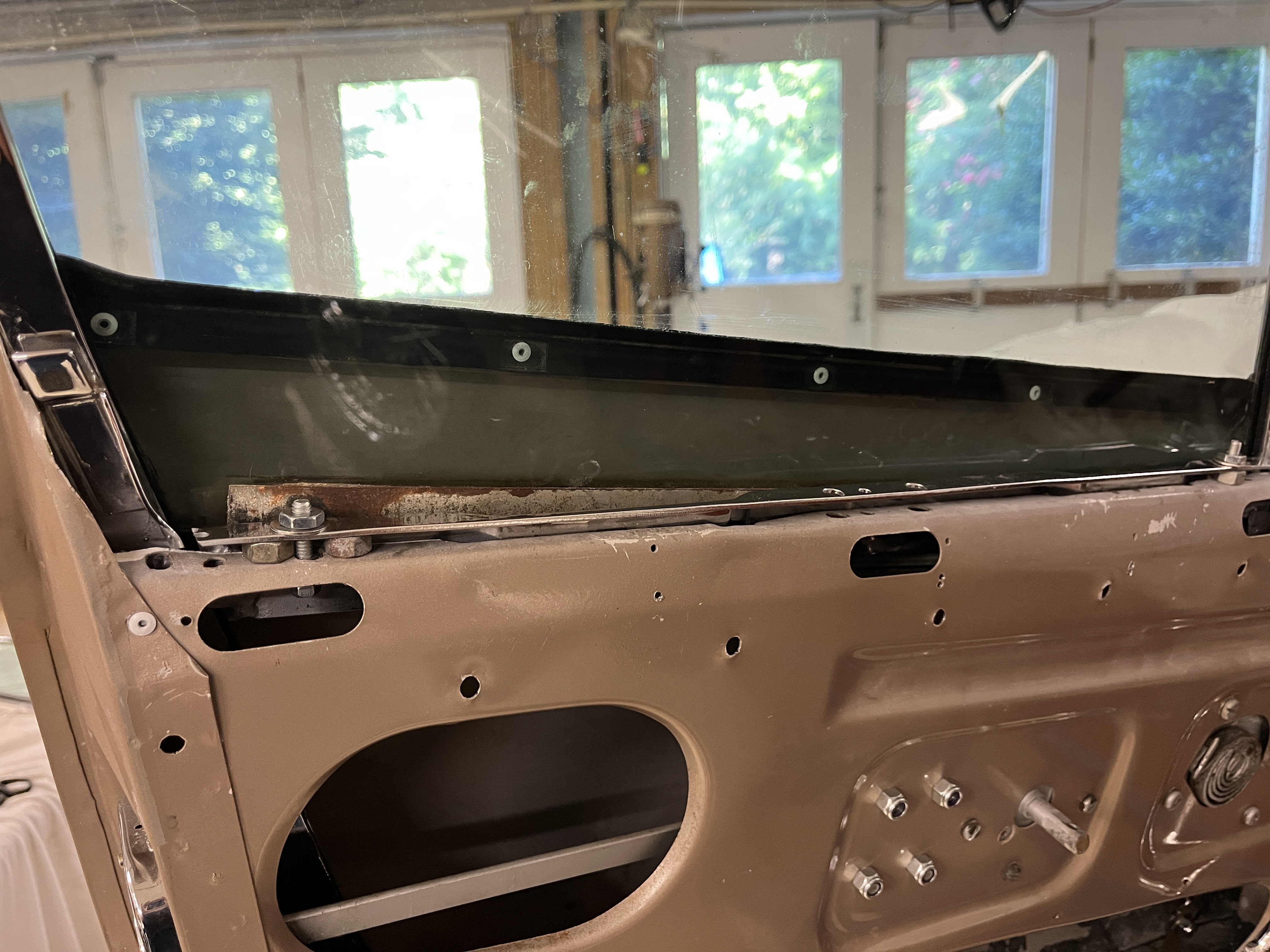
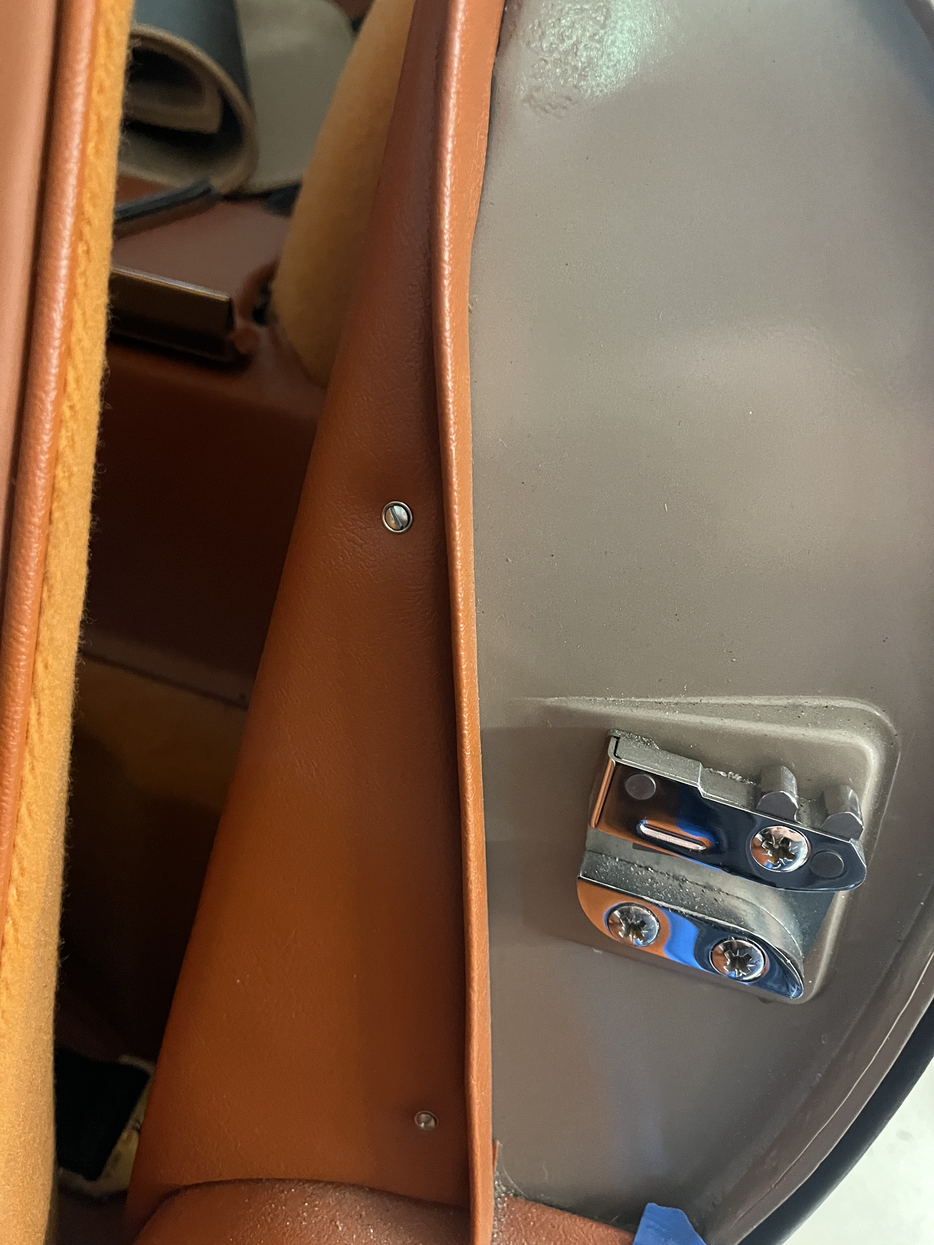
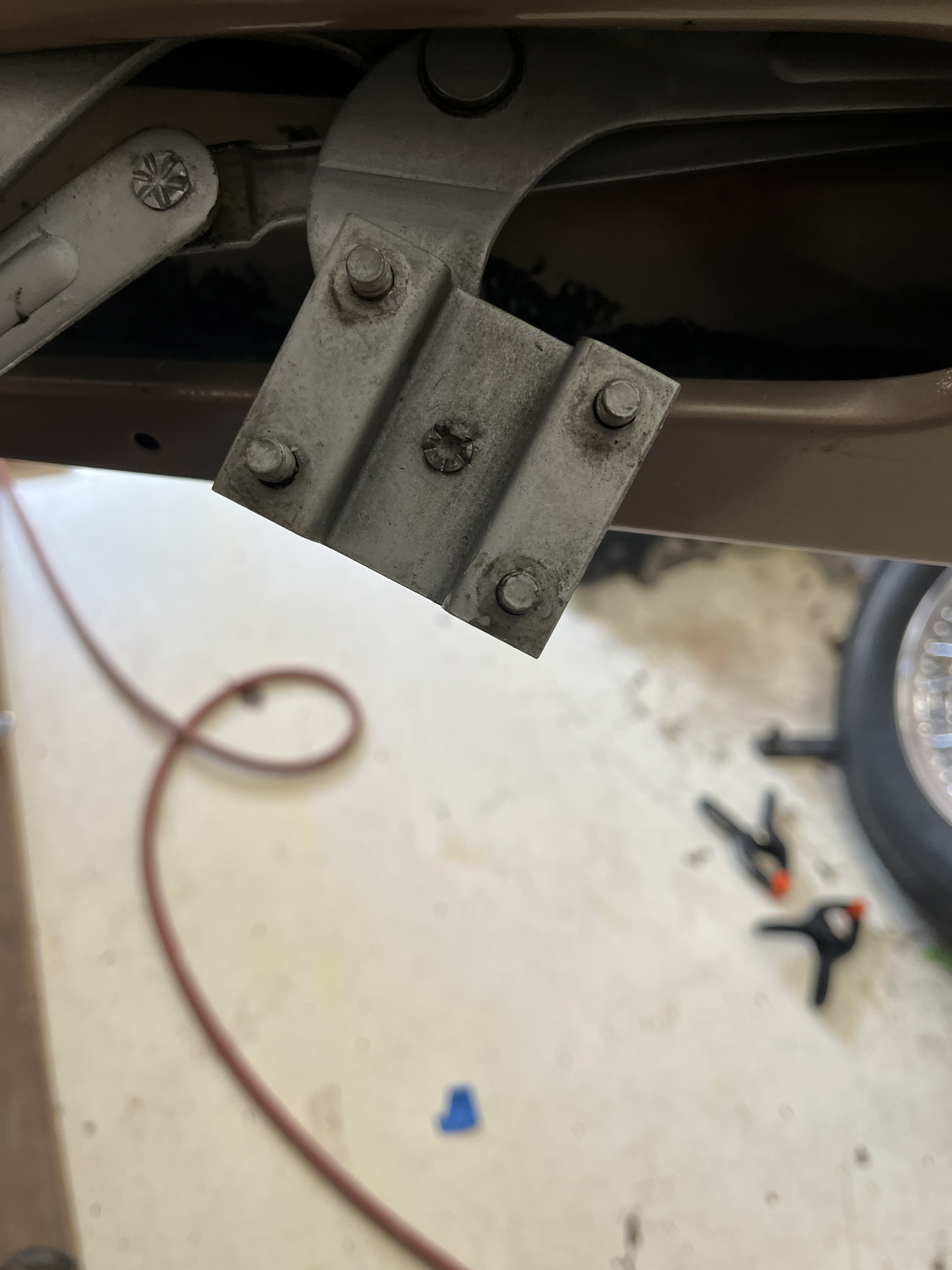
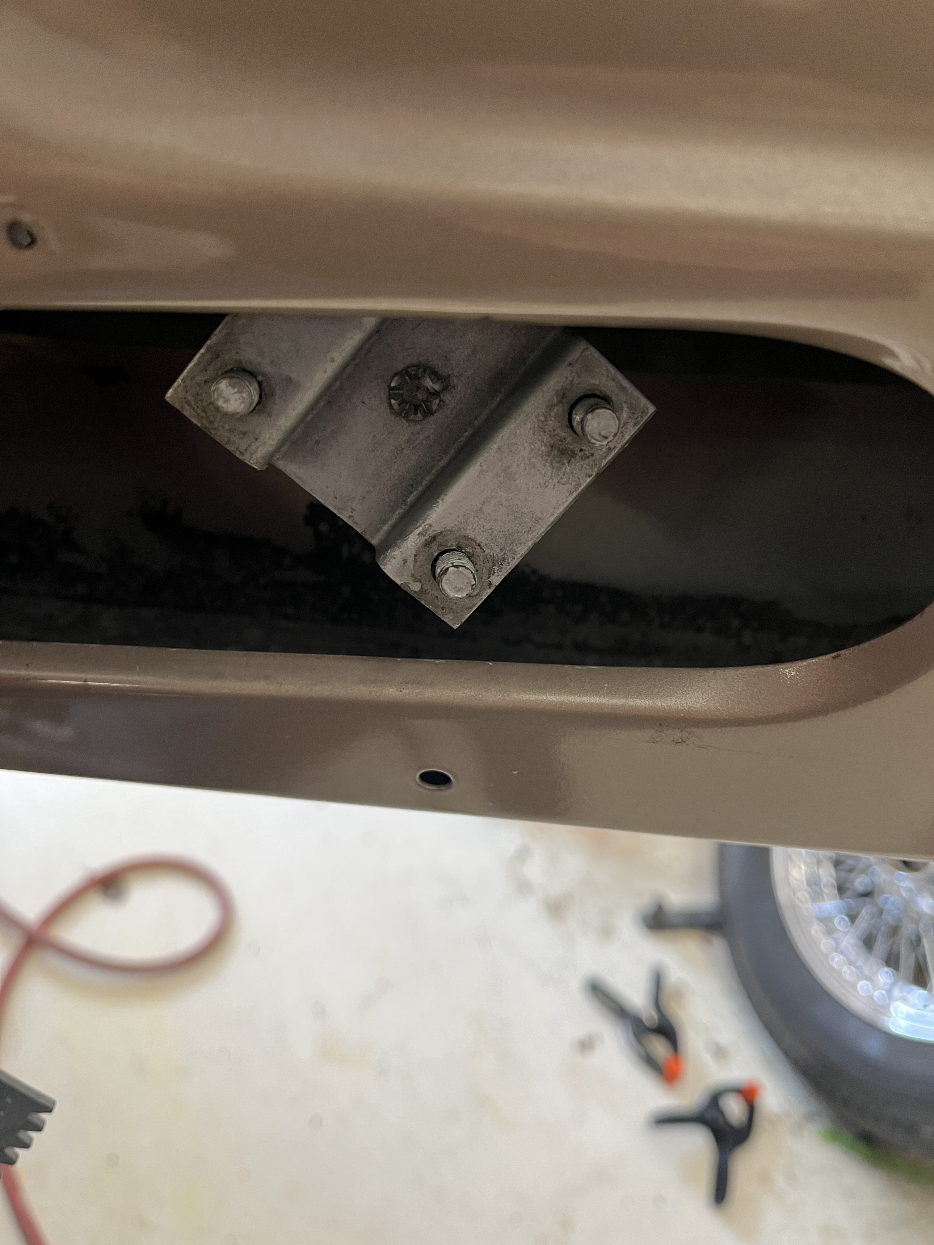
RELEASING THE CHROME FRAME- On the FHC (and maybe on the OTS), once you pull the cap, you will find various screws that pass through a horizontal section of the frame and engage the top of the door inner structure. Carefully note which hardware you are removing to aide in later re-assembly. At the very bottom of the frame, there are two bolts that attach to angle brackets. These are adjustable in the sense that you can push the bottom of the frame inward and outward, with a corresponding opposite movement at the top. This allows some adjustment of the fitment of the door frame at the top, under the drip rail. Get all this hardware removed and you “should” be able to lift the door frame up and out. Warning- it will probably be tight and it will fight you. I removed the glass with the frame. I see no way that the frame can be removed while leaving the glass in the door! You can certainly get the frame most of the way out but that last few inches require that the frame be rotated and twisted substantially so that the bottom of the frame can clear the opening in the top of the door. If the glass remains attached to the mechanism, you can’t articulate the frame as required. I have linked a short video below showing how I install the frame.
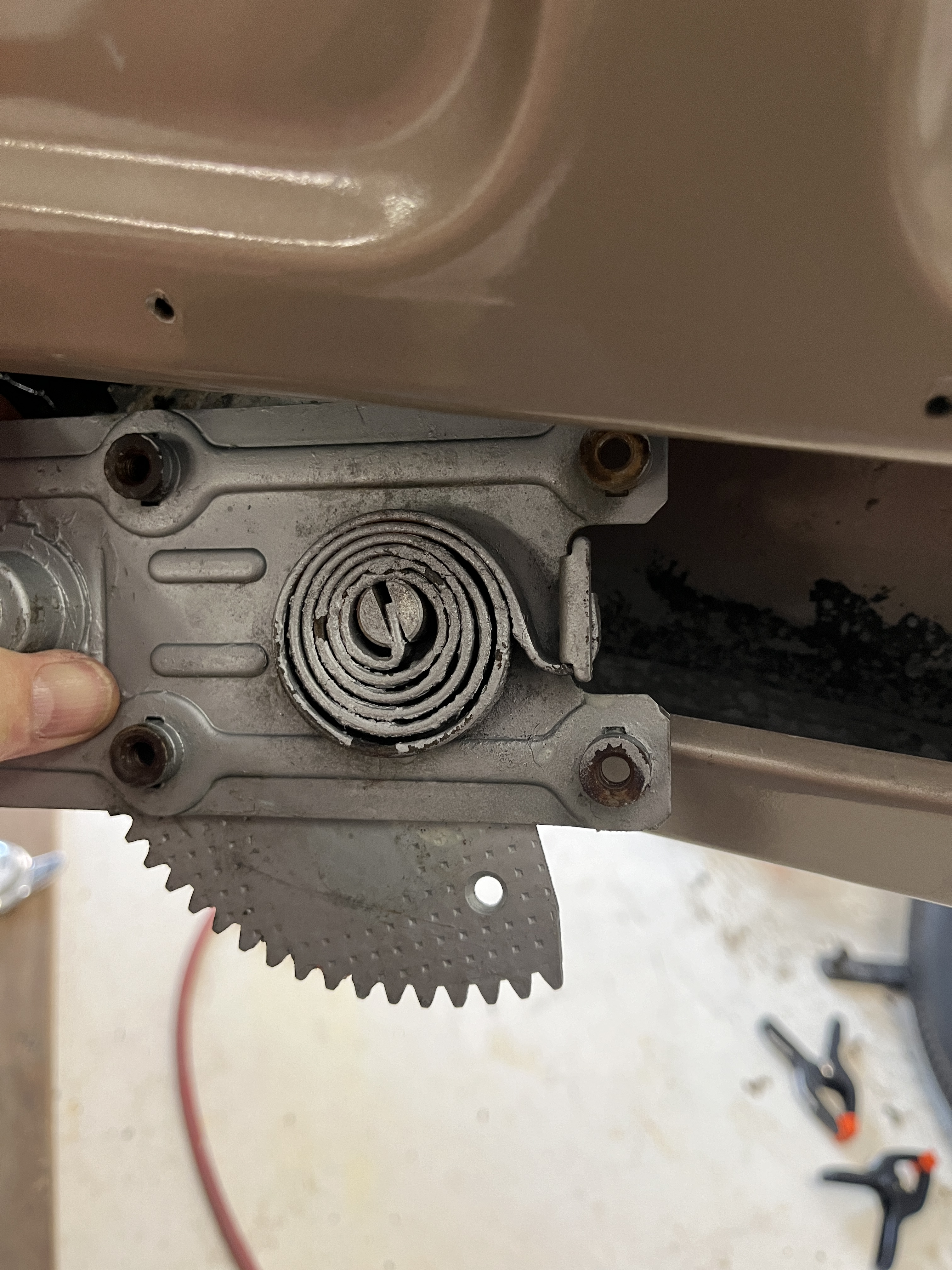
WINDOW REGULATOR MECHANISM- At this point, the door body is mostly stripped of components. The regulator mechanism is attached at two locations. Where the post extends through for the handle, there are 4 obvious screws that must be removed. In the middle of the door, there are four nuts that must be removed. At this point, you should be able to push the mechanism inward, releasing it inside the door cavity. Getting it out is a little bit of a “ship in the bottle” problem. I took a series of photos when I installed it to show one possible path for insertion/removal, which are included below in the photo section. This mechanism was probably not designed for 60 years of use and yours may be a little wobbly at this point. You can certainly clean it with degreaser and add new lubricant to the moving parts. “Fixing it” is problematic. It was not designed for disassembly, as it uses swaged connections instead of traditional threads and nuts. I did have a problem with high rotational resistance at the center pivot, where there is a small plate with 4 studs. I drilled out the swage and went back with a bolt and a nut, so I could adjust the tension. But at the end of the day, if yours is in bad shape, you may just want to bite the bullet and order one of the new reproductions that SNG sells.
DRAINS- One last thing to look for is clogged drains in the bottom of the door body. They are something that many do not even notice but there are two of them. They are flat slots created from a sheet metal tab. A photo is provided below. Make sure they are open so that any water that does make it into the cavity of the door has someplace to go.
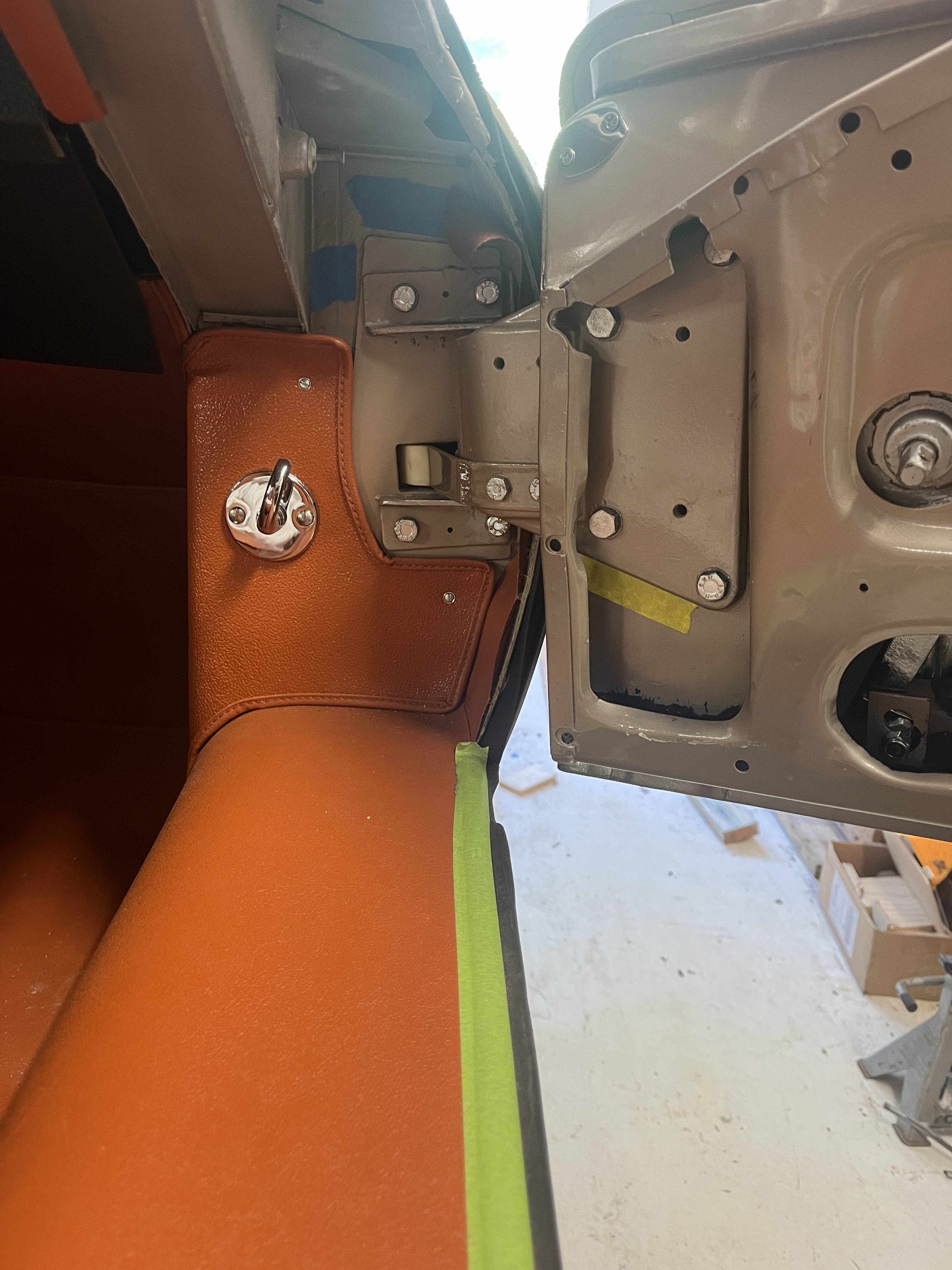
DOOR HINGES- Although not a part of the door assembly, I will touch on the door hinges. One of my first technical articles, written many years ago, discussed Refurbishing an Etype Door Hinge. With the door released from the weight of all its component parts, it is certainly easier to remove and install the door. Indeed, when I am installing a door and am making fine adjustments on the fitment of the door in the body opening, I prefer an empty door. Anyway, there is a single hinge. The first step is to remove the “check strap”. These do tend to break and replacement straps are available from SNG. Do not ignore a broken or missing check strap. If the door is allowed to open beyond its limits, your paint will be damaged on the A pillar! The hinge has four bolts that attach to the door and four bolts that attach to the A post area of the body. They are fairly obvious, although access to the bolts on the door is restricted by the sheetmetal. There may be a 5th smaller bolt on the door hinge. It probably was there to aid the workers on the assembly line. It can be left out during re-assembly. All eight bolts attach to adjustable nut plates. Once you get the door and the hinge off the car, be sure the nuts plates are free to obtain their full range of motion. Also look for any evidence of previous mis-deeds such as stripped threads on the bolts or the nut plates. It might be prudent to “de-tension” each bolt one at a time and immediately “re-tension” it to make sure it is able to take the full force of your hand on a wrench. Nut plates are hard to repair but it can be done.
Looking at a closed door on the car, the hinge that attaches to the door allows the door to be moved a modest amount up, down, forward, and rearward. Rotation is also possible. The hinge on the A post mainly lets you move the door inward and outward. Rotation on the hinge four bolt pattern allows the top and bottom edge of the door to cowl to be adjusted for flushness. It is a “multiple degree of freedom” problem. It typically can take me an hour or so to get a door fitment to my liking. Be especially careful of the interface at the front of the door. Before you remove the door, note that as you open the door the gap reaches its most narrow point with the door open about 30 degrees. For a fresh fitment, always start with the door pushed reward as much as possible. Creep up on moving it forward. That crunching sound that occurs when the front of the door hits the A post sheet metal is not a sound you want to hear!
With an empty door, I work with all eight bolts installed but only two per hinge half tightened. You will see that there are two on each hinge half that a modestly easier to get a wrench on. Work with those as you adjust the door, which may take many trial fit tightnings and loosenings. When you get it the way you want it, you can tighten the remaining bolts. An outline of painters tape around the perimeter of the hinges, preferably before you start, will give you a target and also allow you to be able to notice fine movements that you have made.
DOOR LATCH STRIKER PLATE- Located on the B post, this fixed mechanism accepts the round post on the door latch and grabs onto it. It is attached with 3 screws. There is a single nut plate behind the attachment point that is tapped for the 3 screws. Make sure it has full range of motion and that the threads are in good condition. If necessary, the nut plate can be reached through a hand hole that is behind the upholstered card that covers the inside of the B post and the wheel arch. In a perfect world, the rod on the door latch gently engages the striker plate. In reality, sometimes the striker plate serves to reposition the door, most likely upward, as the door closes. A little bit is OK but obviously there are limits. The striker plate also holds the door flush in the correct position. Depending on the condition of your latch, rubber seals, hinges, etc. this may be easily obtained or impossible. I can’t go into all the possible issues but take a look at the “star wheel” on the latch. They can become loose. If they have too much “lost motion” the door will spring back and not be flush. There is also a “click-click” in the latch. First click the door is not fully closed but won’t fly open. The second click the door is fully closed. Again, if there is too much lost motion between the clicks, you can’t get the door to engage flush to the bodywork.
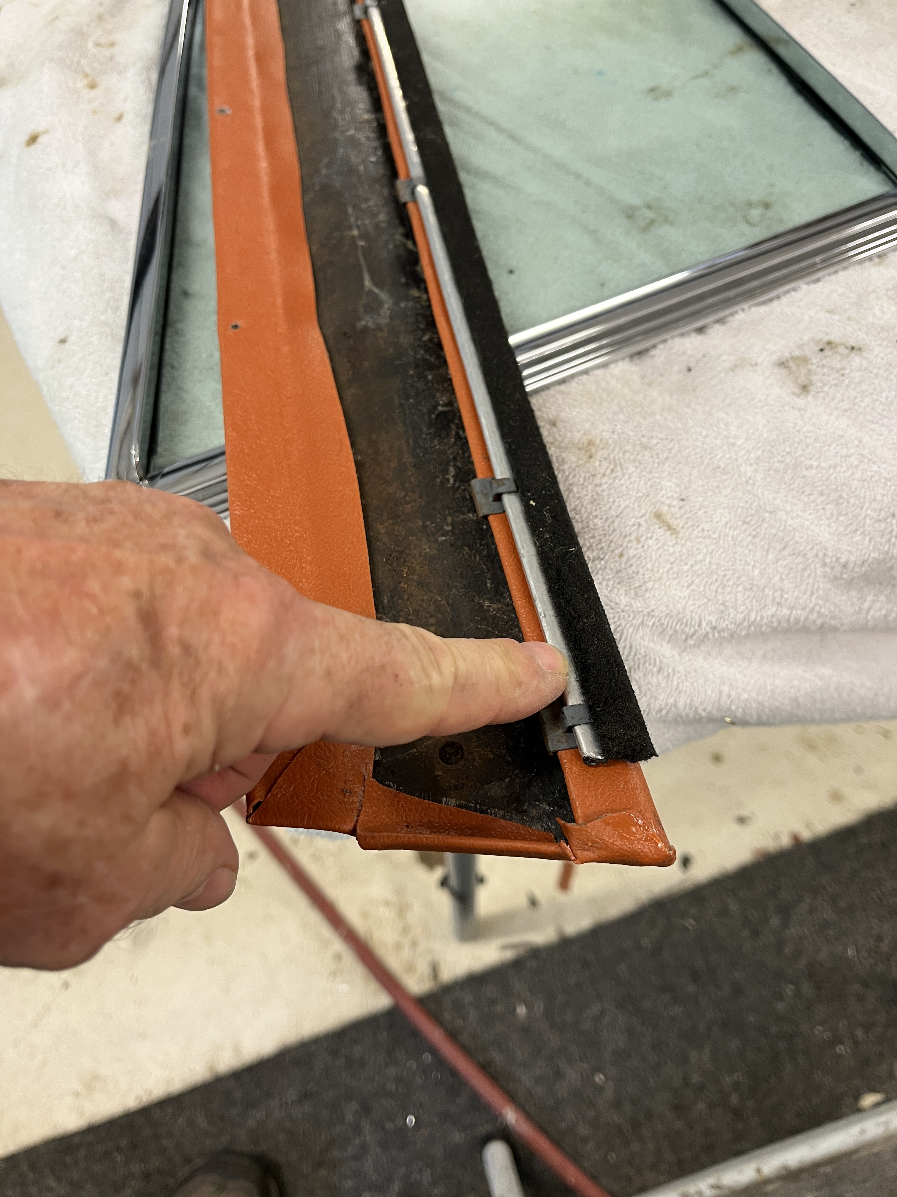
DOOR FRAME FELT- There is a felt product in the chrome door frame. I had my door frames chromed and replaced the felt. SNG sold me a roll of felt. In general, the felt is a little wider than you need. As you push the flat width of the felt (about 2″) into the groove of the frame, it will form a U shape. I notched the one 90 degree corner, put in a light amount of rubber gasket adhesive in the groove, pressed in the felt, and provisionally installed the window glass to compress and shape the felt. After a bit, I used a razor blade to trim the felt. SNG also sells a pre-formed product, which I found out about after the fact.
ASSEMBLY- At this point, I have generally described all the dis-assembly steps so assembly should just be the reverse, right? Well- maybe, sorta, etc. Assuming you have carefully read the above, here are some suggested steps for assembly.
-For a new installation, consider installing the rubber seal that runs up from the front edge of the door and across to where the seal transitions to the A post. That particular seal is very had to get to with the door hung. Conversely, once you get onto the A post and across the top of the door, you don’t want to have the seal installed until you are sure you are done with your cantrails. The cantrail attachment screws are under the seal.
-Hang the door shell. You probably want to provisionally install the latch and striker plate to help verify alignment. For new installations, I like to see a good fit with minimal or no seals. So you will know that you are not going crazy when you start adding seals and the door doesn’t want to close correctly!
-Test fit the chrome window frame. I was not totally shocked to find that the chrome window frame does a poor job of mimicing the opening in the body shell. Ditto for the quarter window frame. It is during these types of fitment that you understand that these body shells are not perfect dimensionally. During my initial fitment of the window frame, the gaps at the top, with respect to the “drip rail” varied from almost nothing to 3/8″. The “almost nothing” was going to be a problem, as it left no room for the chrome trim on the drip rail and the rubber seal installed on the outer edge of the window frame. I was forced to make major modifications to the window frame in order to give myself a decent gap. That said, the normal condition “should” be that there is some excess gap, which can be reduced to a best fit value using shims. I only wish that had been my problem!
-Install latch on the shut face of the door. Easier with the window frame not installed but certainly possible with it installed. I would note that I had a problem, once I installed the window frame, the “arm” on the latch interferred with the window frame. Carefully bending of the arm got everything working as required.
-Install the outer door handle. Check for operation with respect to engaging the latch. There is an adjustable bolt on the end of the latch “push” that can be run in or out to get the optimum clearance.
-Install the mechanism for opening the door with the inside handle.
-Install the striker plate on the shut face of the door opening. Check for operation.
-Test fit the glass to the window regulator mechanism. So that you understand how these two parts connect together and to make sure they will fit together, lay the glass and the mechanism on a work table. With some experimentation, you should start to understand how the two rollers on the mechanism engage the track that is bonded to the bottom of the glass. You will see that the rollers are spring loaded and they both have to engage the track at about the same time. Having four hands at this point would be nice! But again, understand how it works, because you will have to do it again with everything installed in the door, under more cramped conditions.
-Install the window regulator mechanism. Do a quick check, temporarily installing the inside handle, to make sure it cranks up and down smoothly. Trust me, it will get worse as you add the glass to the equation but at least make sure that there is no binding without the glass involved.
-With the door frame on a work table, install the glass into the frame. Make sure it moves smoothly for its full range of motion.
-Install the window frame, with the glass in the full up position, loosely into the door.
-Connect the glass to the the regulator mechnism. Here is where it gets tricky, especially for a FHC. Because of the controlled articulation of the regulator mechanism, there is only one spot, at the top of its upward travel, where the rollers will line up with the end of the track on the glass. To get to this point, the window glass must be higher vertically than normal, by about an inch. To do this on the FHC, you must lift the chrome frame upward by a small amount. Having two people at this point is a big help, although I learned to do it myself with some practice. It just takes some trial and error, so to speak. Once you have the rollers engaged, you will lower the glass a bit and this will allow you to seat the chrome frame in its final position. Install any shims and the retaining screws that hold the frame to the door body.
-Check the range of motion of the glass by raising and lower it. I don’t know why but I had some strange interferences when I did this. Hopefully yours will be fine but be prepared to do some “fettling”.
-Check the latch mechnism for interference again, now that you have the window frame installed.
-Provisionally engage the frame at the bottom of the two vertical legs, with the small angle brackets and bolting hardware. You should see that the brackets have slotted holes which will allow some tilt at the top of the frame.
-Install the rubber seals around the door. This is such a simple sentence. In my case, there was nothing simple about it. The best I can say is that the seals represent a starting point, upon which you must do a custom fitment. Be prepared to modify the seals. I used razor blades and a bench grinder. I know some say “why can’t I buy seals that fit?” Well, because we are working with a quasi hand built body shell that was built at a price point that made it affordable but maybe not dimensionally consistent. As I noted above, the varous gaps can and will vary over a wide range. I just do not see that there is a one size fits all solution when it comes to seals. I will note that at the time I did my car, the forums seem to like the seals coming out of COH Baines in the UK. The manager at SNG-US told me that they sourced their seals from COH Baines, when possible. As a consequence, I bought all my seals from SNG. I worked very hard at allowing the door to close without “slamming”. I probably erred on the side of smooth operation and will not be totally surprised if I later find some air or water leaks. It is a compromise that you will have to decide how to handle. One thing that I do like to do is to insert a sheet of paper locally at the various door gaps, close the door, and give it a tug. Doing this, you will certainly be able to recognize gaps and as you develop a feel for the risistance to your tugging, you should be able to evaluate tight spots. I spent a lot of time of the doors and seals. It comes with the territory!
-Install a plastic vapor barrier on the inner door face. I will note that it seems that everyone does this but frankly, the efficacy of this escapes me. The plastic gets punctured with multiple holes from the various handles, screws, and clips on the door cards. It probably slows down gross water transfer but that is about it.
-Install the upholstered door cap and the door card. Pro tip- place small pieces of painters tape on the outside of the door card, roughly over the position of the clips. Generally, if the clips are lined up, you can strike the spot with the tape with the palm of your hand and pop the clip into place.
-Install the handles. FYI, the diagram in the Spare Parts Catalogue for the 3.8 cars shows the door handle pointing straight down.
This should have you back to a completed door assembly! I am going to do a separate article on the door cards and the quarter windows so keep an eye out for that on my website. As I noted at the beginning, I am placing my photos here at the end, which helps me keep the flow of the text going. I hope this helped!
Note- If you are looking at the Spare Parts Catalogue (SPC) most of the items required for the door are shown on Plate 40 for the OTS and Plate 48 for the FHC, for 3.8 cars. Plate 41 for the OTS and Plate 50 for the FHC, for 4.2 cars.


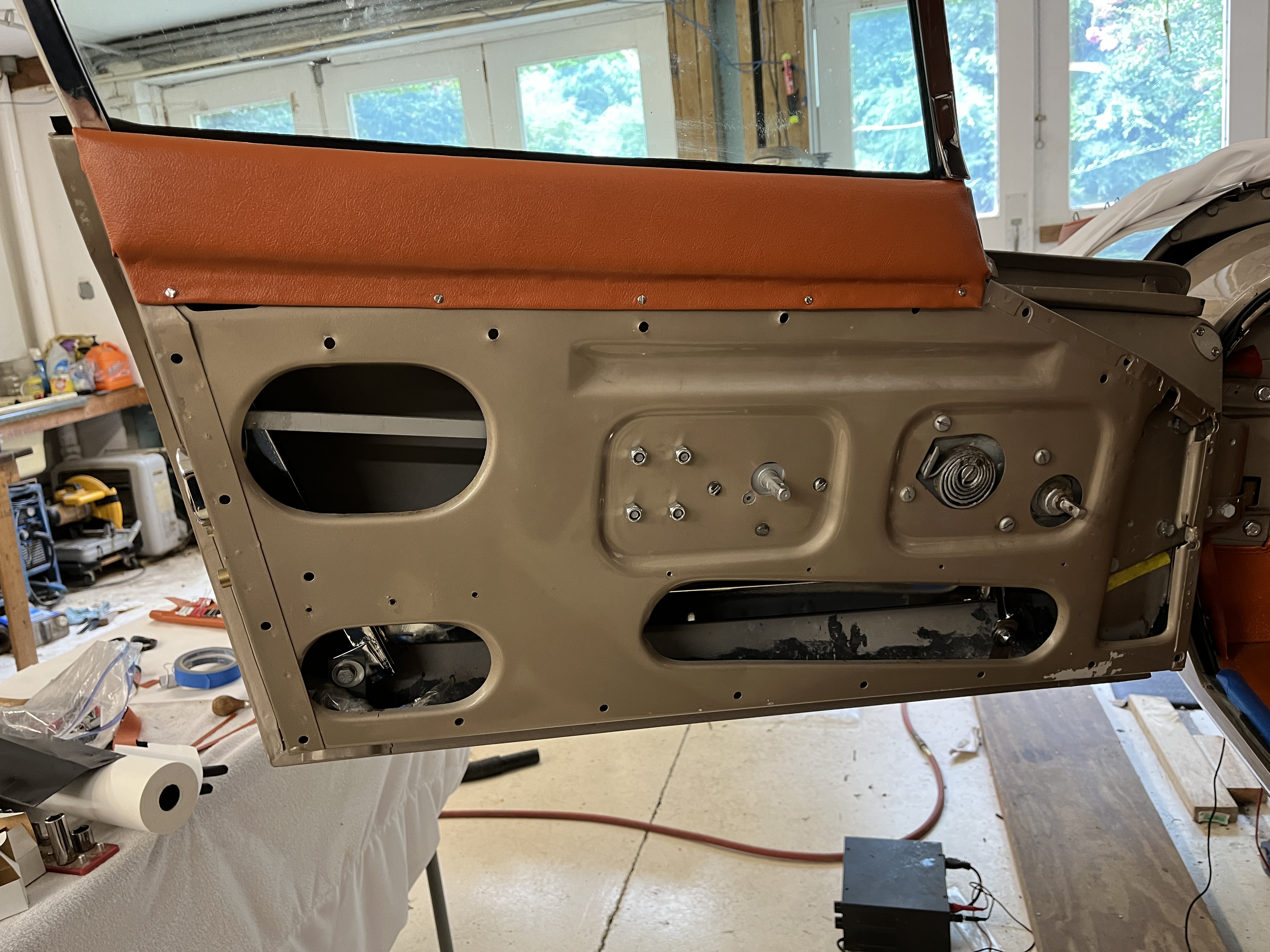
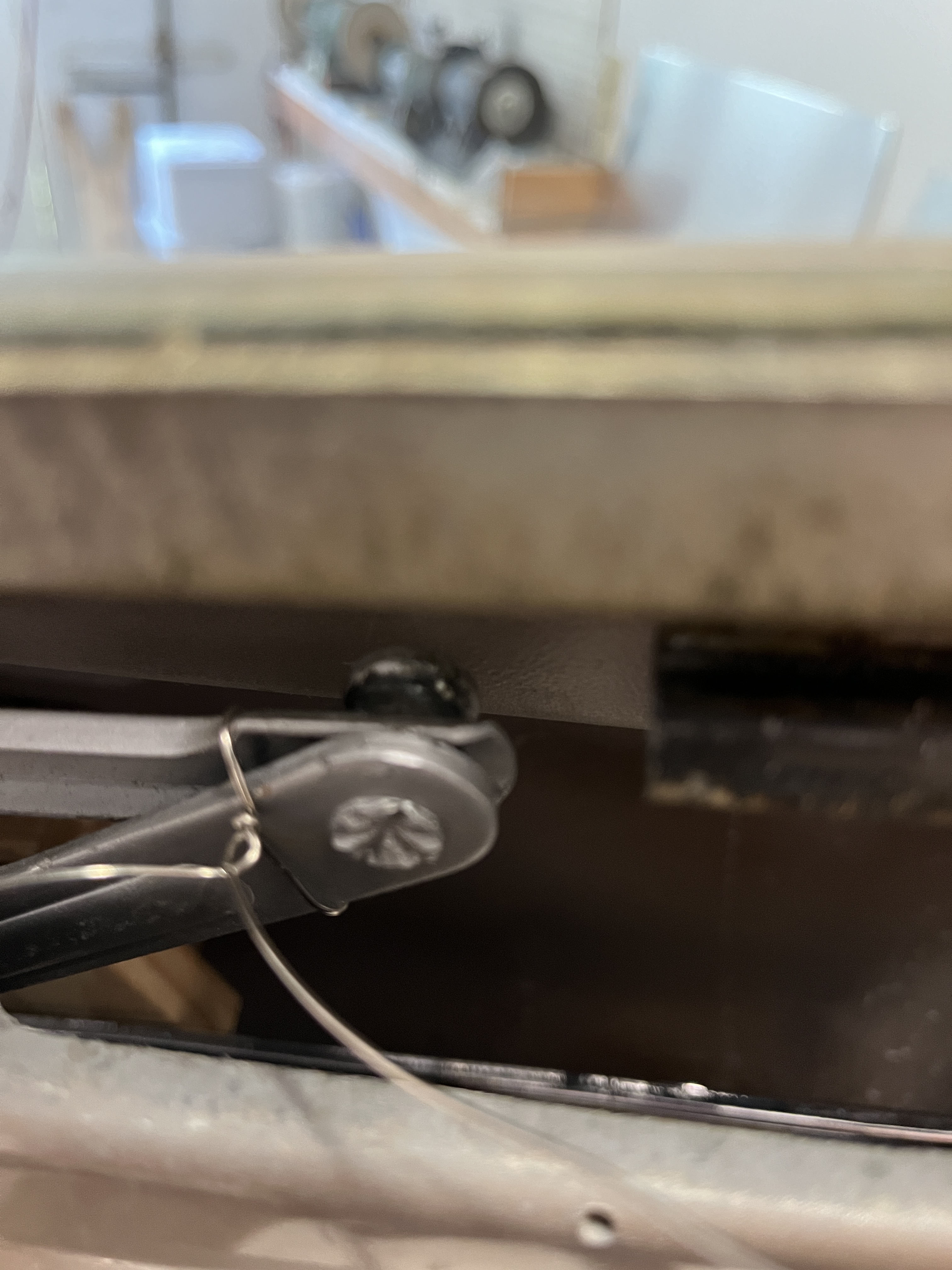
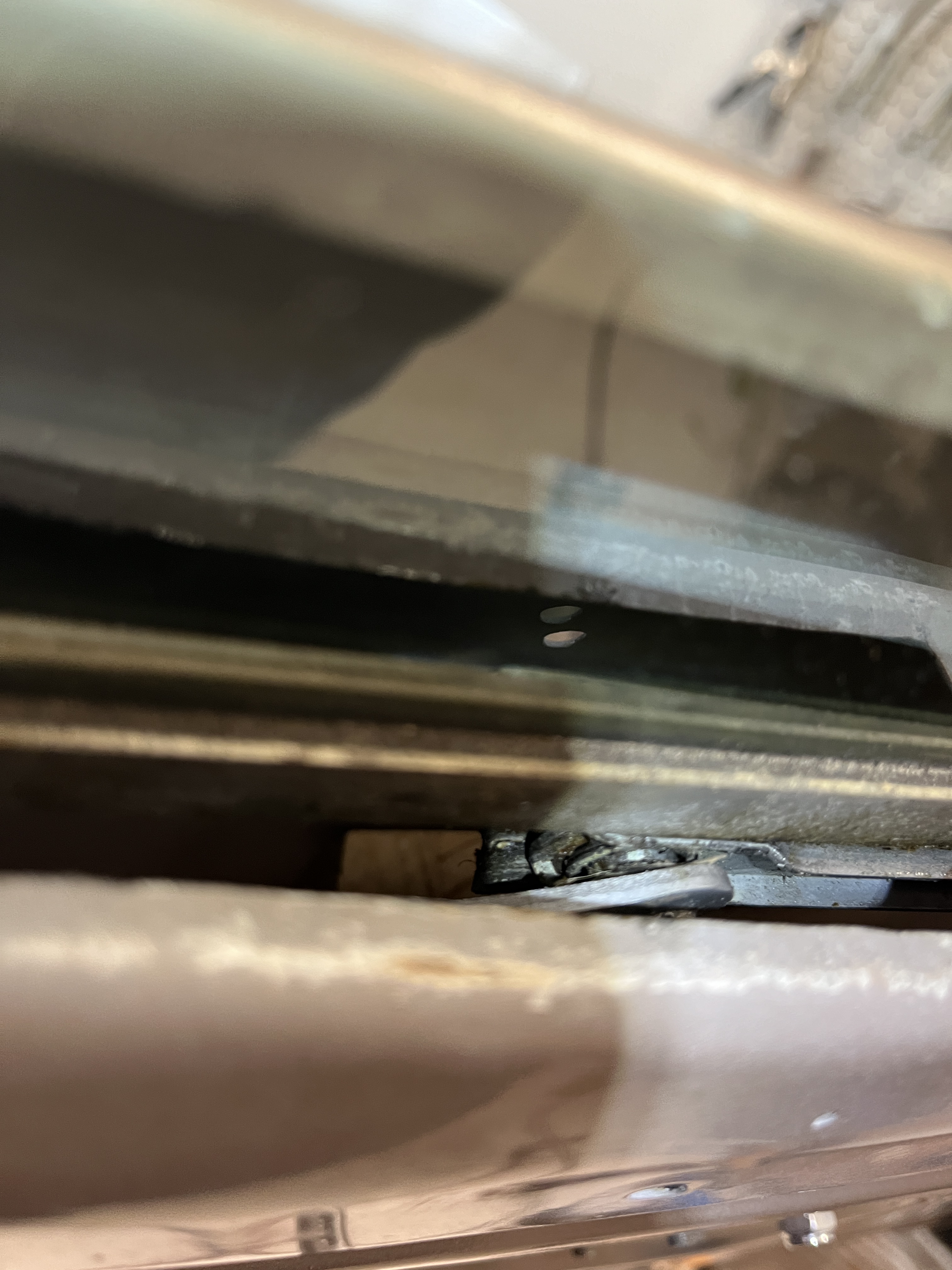
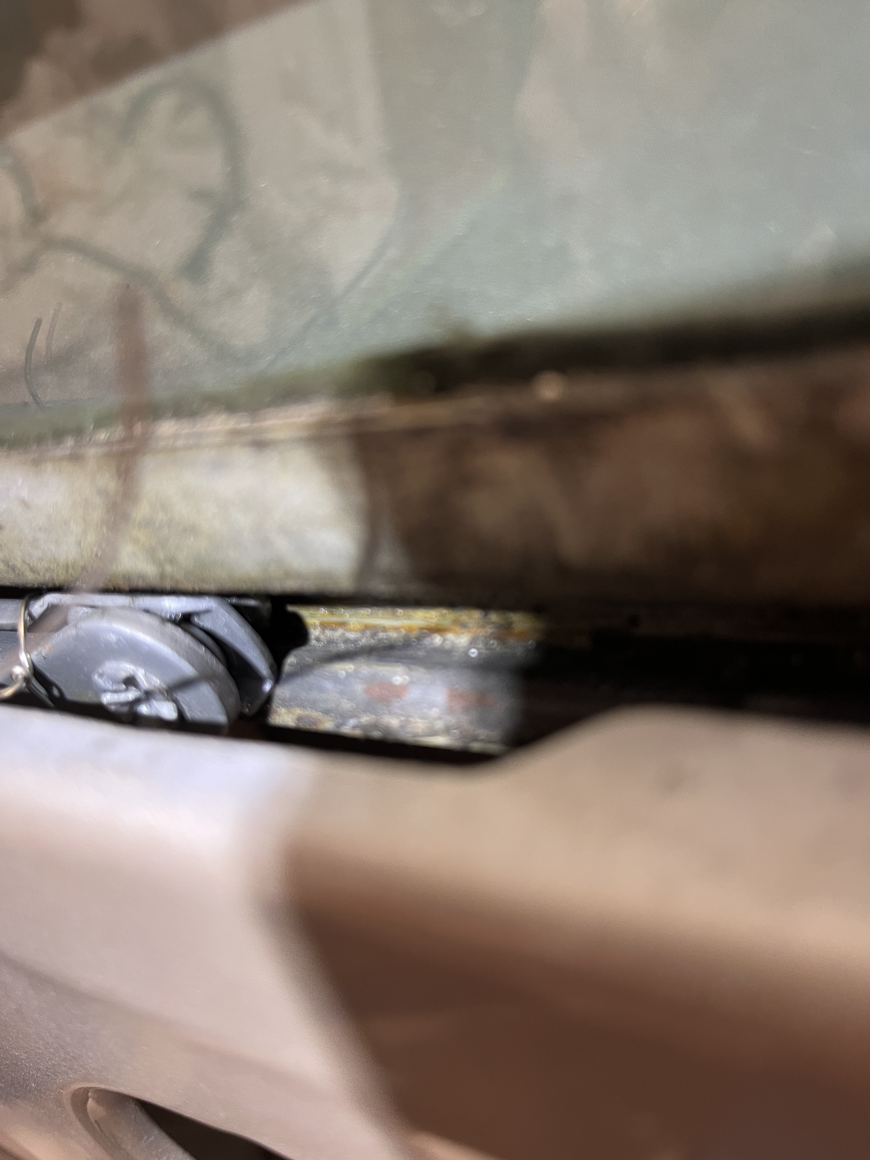
The following photo sequence shows how I installed the window regulator.


Discussion
Comments are closed.