For various reasons, it has taken me a while to get started with the re-assembly of the engine. But progress is finally happening.
Previous article in this series – Machine Work Done
Next articles in this series – Tour of Engine Sensors and Components and Engine -Re-Assembly Part 2
I am going to start by saying that before I started this project, I purchased the M96/97 engine assembly tutorial video from Jake Raby. I had been looking at Jake’s offerings for several years, which involved coming down to his shop in Georgia and attending a hands-on class. But it was expensive and I really didn’t have an active need to gain this expertise. My wife’s Cayman S was running fine so it would have mainly been an expensive response to my natural curiosity on the subject. But when I purchased my 2007 Cayman S with 100K miles, my interest become more active. And Jake now offers a video that avoids all the time and travel expenses. You may instinctively baulk at the price but I am here to tell you, it is one of the best investments I’ve ever made! The education value is priceless and frankly there is nothing else like it that I have been able to find. So I am going to say, if you are looking to rebuild one of these engines, Buy Jake’s Video! You won’t regret it.
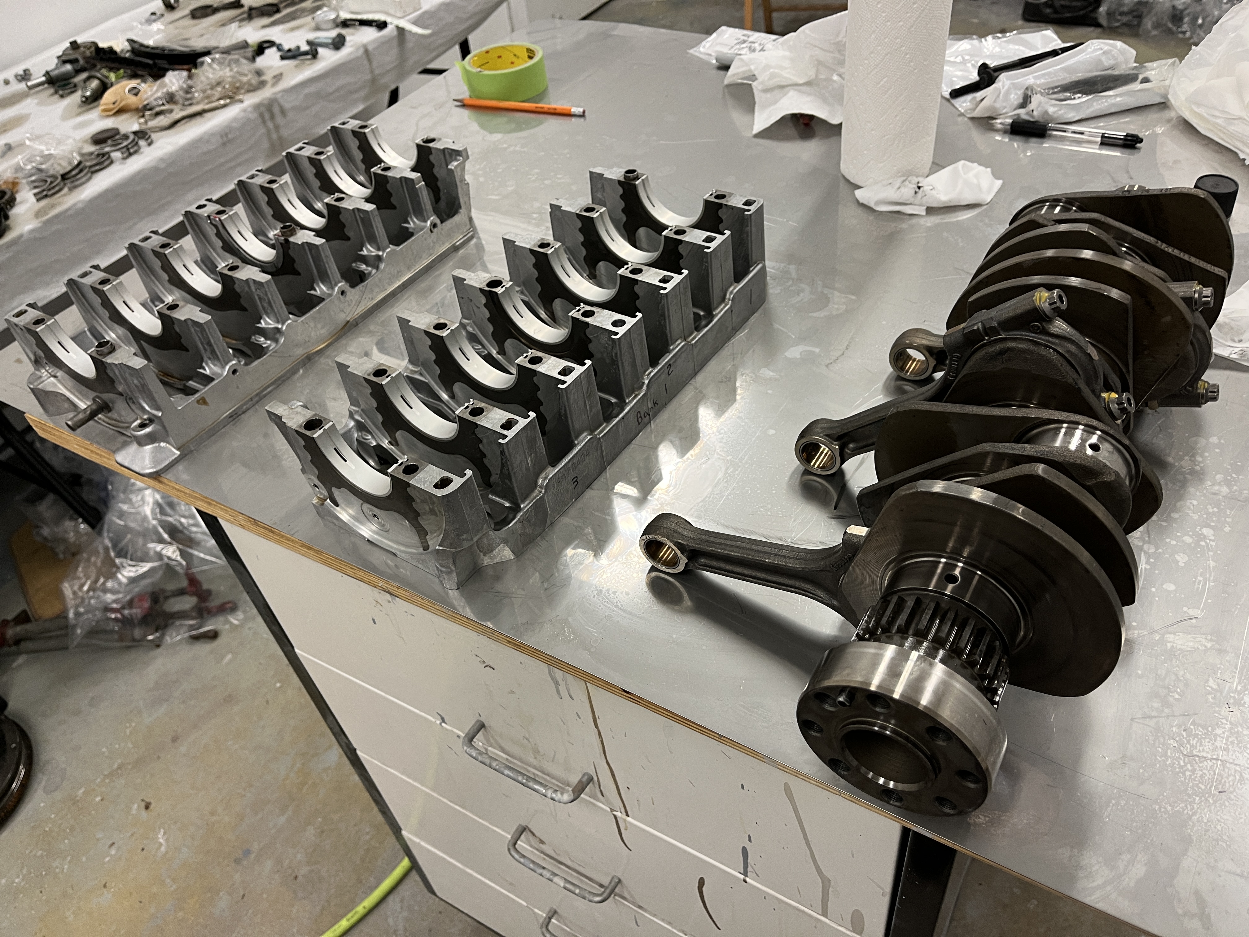
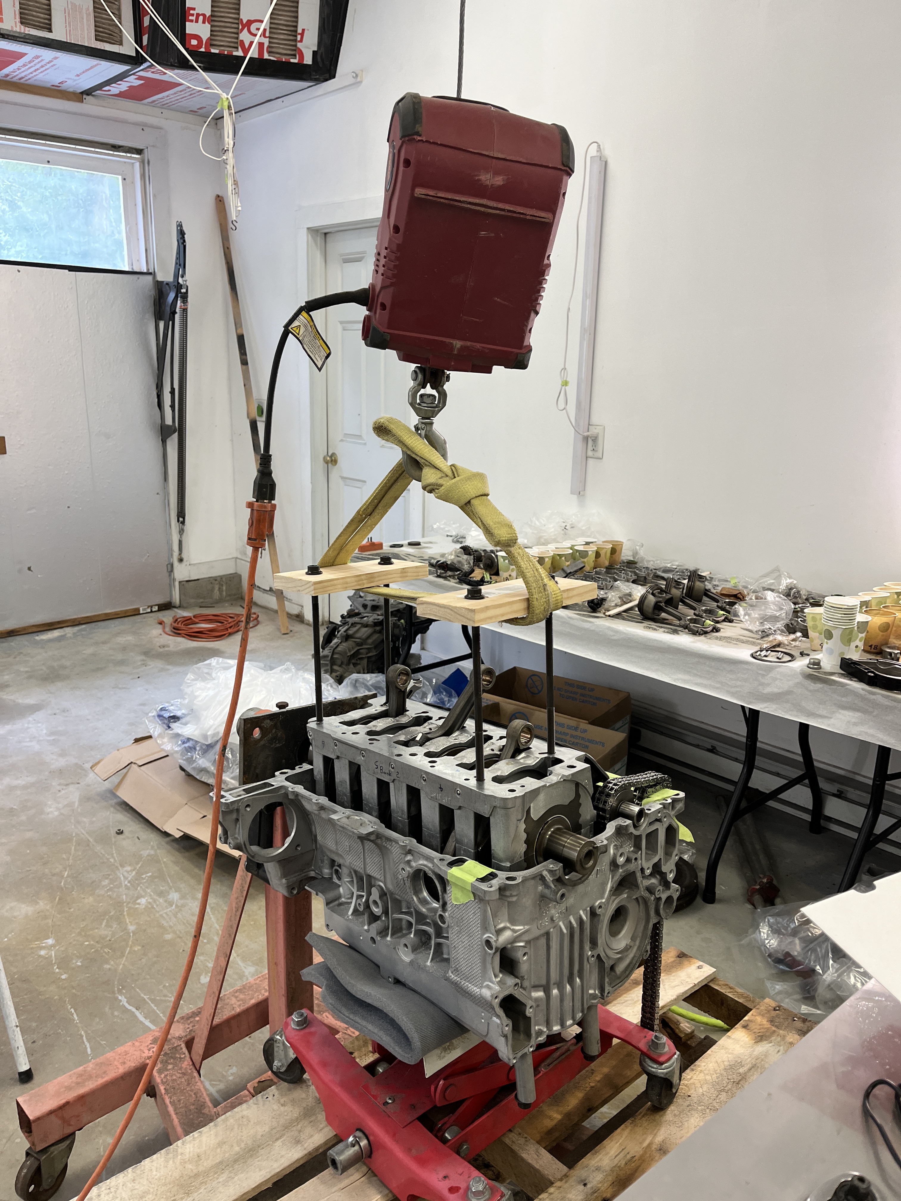
So with that as a backdrop, I watched the video last spring (full running time is many hours) to get a general familiarity of what I was up against. Then I selected my machine shop, Slakker Racing Development (SRD), and got that effort underway. That included an order for the bulk of my rebuild and upgrade parts package. When the parts and machine work arrived, I repurposed my paint bay into an engine build bay. This was an easy switch, as the paint bay is basically a clean, well lit, heated and cooled garage bay. It was perfect for building an engine. I moved a cabinet into the middle of the room and topped it with a sheet of stainless steel plate that I had squirrelled away. BTW, the stainless steel plate makes a perfect work surface as it is smooth and can be wiped down early and often to keep that work area as clean as possible. I rigged an electrical hoist, which serves as the “second person” that Jake calls for in some cases. I also brought in an engine stand.
I spent a few days watching the Jake videos again to identify a final shopping list for parts and tools. Of course I found a few things that I needed. But eventually I got started.
The way I am going to handle my discussion of the assembly process it to start by saying that I can in no way describe it better than Jake’s video does. No Way. I am going to offer my own list of Assembly Notes, which basically represents things of note that came up for me that might be useful information. And I will throw in a bunch of pictures! BTW, Jake’s video does not address engine removal from the car, teardown, or installation of ancillary components. For that I used a bootleg pdf of what I understand is the text image of what a Porsche technician sees on his laptop when using the Porsche PIWIS, which stands for Porsche Integrated Workshop Information System. It is a little clunky as the actual system “hot links” you to where you need to be, whereas the pdf I have is jumbled up. But as you get used to it, it will tell you the steps for engine removal and re-installation. It also has valuable information regarding torque values. And since I recognize that it is a bootleg, I’m just going to have to leave it up to you to find your own copy on the web, since I don’t want the liability of sharing something like this.
First and foremost, Do Your Homework. If you are like me, this is your first rebuild of a Porsche M96 or M97 engine. If you have never re-built an engine of any kind, this may not be a good place to start. In my case, I have rebuilt engines, starting when I was a teenager. A lot of the concepts presented in Jakes videos are familiar to me, with as they say the devil being in the details. It is not an exageration to say that I spent 5 hours thinking and prepping for every 1 hour of work. I realize there are few things that if I screw up are going to be very costly. And there are other things that, though annoying, can be recovered from. So take your time and get familiar with each step.
I hope you will find this level of discussion useful. This job is not for the faint of heart but if you enjoy a technical challenge, I think this is a good a challenge as any.

Engine Assembly Notes
- Get your crankshaft checked. I took my crankshaft to a local machine shop to be checked. They can check it for straightness and will measure the diameter of the main and rod journals. They will ask what the diameter spec is and as far as I can tell, Porsche does not release these numbers. But you can at least have them check to make sure they are all about the same value. And if any have been damaged. Then go ahead and get them to polish the journals.
- Check your crankshaft bearing clearances with Plastigage. I did this for my main bearings. It is basically a precaution. Again, Porsche does not publish specs but you can at least see that the clearances are all about the same. I did this with my clean unlubricated crankshaft and the new unlubricated bearings. You should only torque the carrier bolts to a nominal value, 15 ft-lbs or so.
- Only rotate your crankshaft after full torquing. OK, true confession time. As I recall, I dropped my crankshaft into the carrier, all bearings with assembly lube, and tightened the 14 carrier bolts hand tight. I then tried to rotate the crankshaft. It was impossible to rotate until I actually mounted the flywheel to give me some leverage. Not really understanding what I was dealing with, I went ahead and torqued the carrier bolts to 120 degrees rotation. Lo and behold, the crankshaft rotated easily. As best as I can surmise, the crankshaft carrier is line bored with the carrier bolts fully torqued and it is not quite round in its relaxed state. But I really don’t know. Anyway, after thinking about this for a few days, I got nervous and decided to pull that carrier back apart and inspect the main bearings. They all had a strange mark, for lack of a better word, near the parting line. Was that caused by rotating the crank by hand with the aid of the flywheel? Again, I don’t know. But I decided to be conservative and I ordered a new set of main bearings and carrier bolts. Ouch. But I will sleep better. During the subsequent assembly cycle, I did not rotate the crankshaft until the torque was fully applied and it rotated as smooth as buttah!
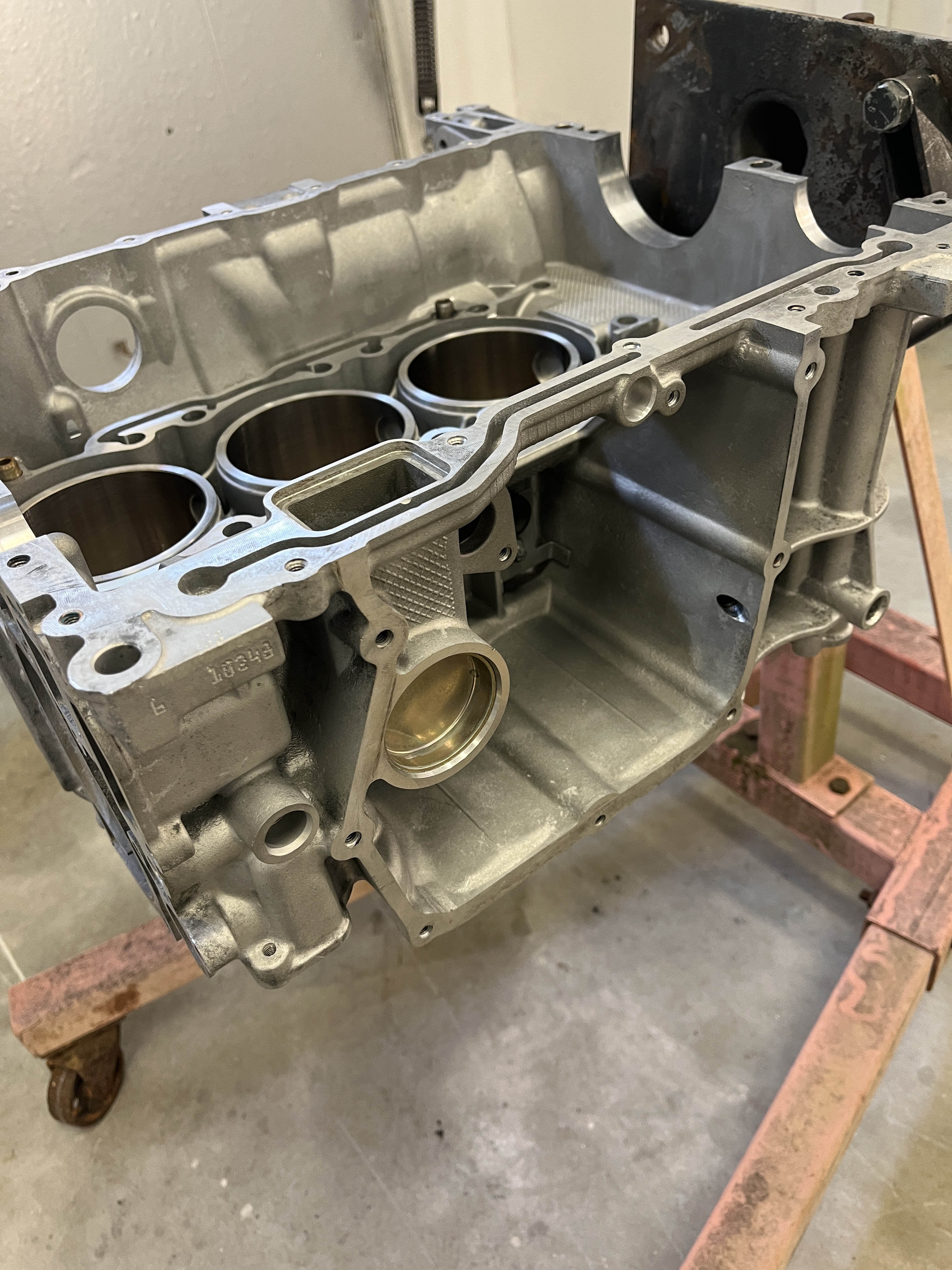
- Engine stand spider attachment. I spent a lot of money on this build but somehow I baulked at spending $1000 on a custom spider type attachment for my engine stand. I was pleasantly surprised to find that one of my Harbor Freight heavy duty engine stands had attachment spiders that provide some space at the flywheel and reach to the available attachment points on the end of the block halve. And herein lies my warning. The available holes on the bank 1 block halve are not well spaced. With the block facing down, as required to install the crankshaft carrier, the overturning moment reaction force is placed entirely on one bolt hole. And that hole is a lug. My nightmare scenario is that the lug would snap off. I reduced my risk by placing a transmission jack under the other end of the block to support the weight. I only removed this jack when required. Fortunately, when you rotate the engine +/- 90 degrees, the physics of the mounting holes is much better. And once I get the other case halve installed, I will re-attach the engine stand spider legs to get a better pattern. I looked closely at video of Jake’s stand and I think they have the same problem. I guess they do it all the time but just maintain some awareness that the block is especially vulnerable when you are installing the crankshaft carrier.
- Torque values. You may notice that Jake is careful not to mention any torque values. “Torque to value” is his catch phrase. I understand, as his one video is covering a range of engine families, etc. In my case, I am using my “bootleg” Cayman shop manual to find applicable torque values. It is a little bit of a treasure hunt but they are in there. I think this is what Jake did with his little book of torque values. Unfortunately, the book does not directly address the Cayman. Thus, I used the shop manual. For my ARP rod bolts, I got my values from the ARP website.
- Assembly lubricants. You may also notice that Jake is careful not to mention specific assembly lubricants. Again, I understand. If you have SRD do your machine work but want the challenge of doing your own assembly, simply ask them to include the lubricants that they use for their in-house builds as part of your purchase.
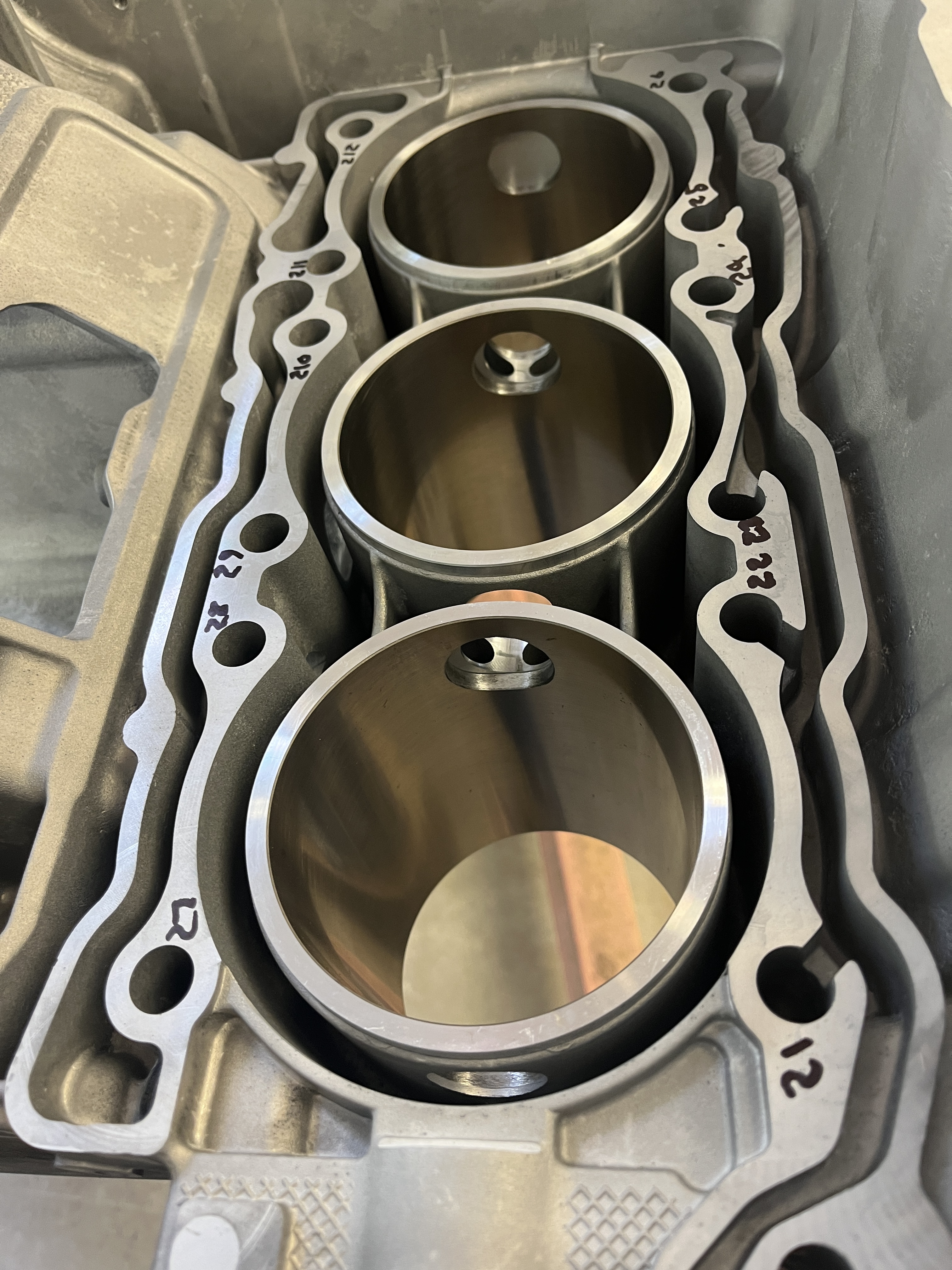
- Check dowel pins in crankcase carrier and cylinder halves, as Jake recommends in his video. For me, the ones in the cylinder halves went missing at the machine shop. I wound up ordering more from McMaster. No biggie but 2 of the holes in the bank 2 cylinder half had shallow holes compared to the others. Even after I cleaned out the holes all the way to the bottom. The 22 mm long ones shown in the PET were too long. I wound up ordering 14 mm long ones. This may explain why Jake discusses this in his video!
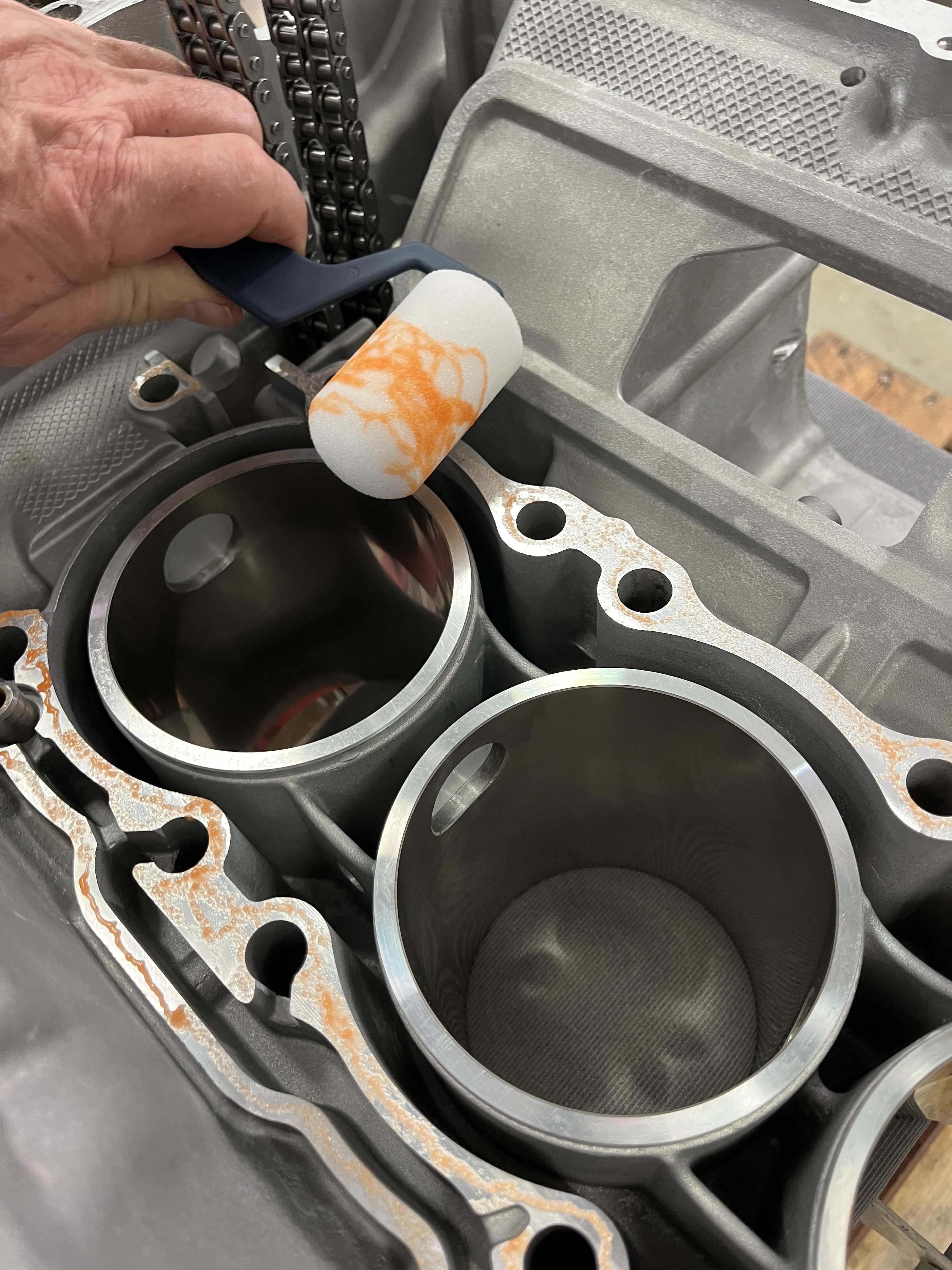
- Loctite 574 for the crankshaft carrier. OK, this is a little bit of a sleeper issue. If you watched my video on the oiling system, then you are a certified Engine Nerd! If you can recall, the crankcase half is a machined fit to surfaces on the crankshaft carrier, with oil passages trapped between the two surfaces. There is a similar arrangement on the 944, where the crankshaft girdle has the oil passage from the pickup tube to the suction of the oil pump. On the 944, the factory seals this interface with Loctite 574. Per the Loctite literature “LOCTITE® 574 seals close-fitting joints between rigid metal faces and flanges. The product cures when confined in the absence of air between close-fitting metal surfaces.” With all the angst about oil pressure on the Cayman, it seemed like a no brainer to seal this interface. Brandon at SRD confirmed that Hartech does the same on their rebuilds and that SRD is doing the same.
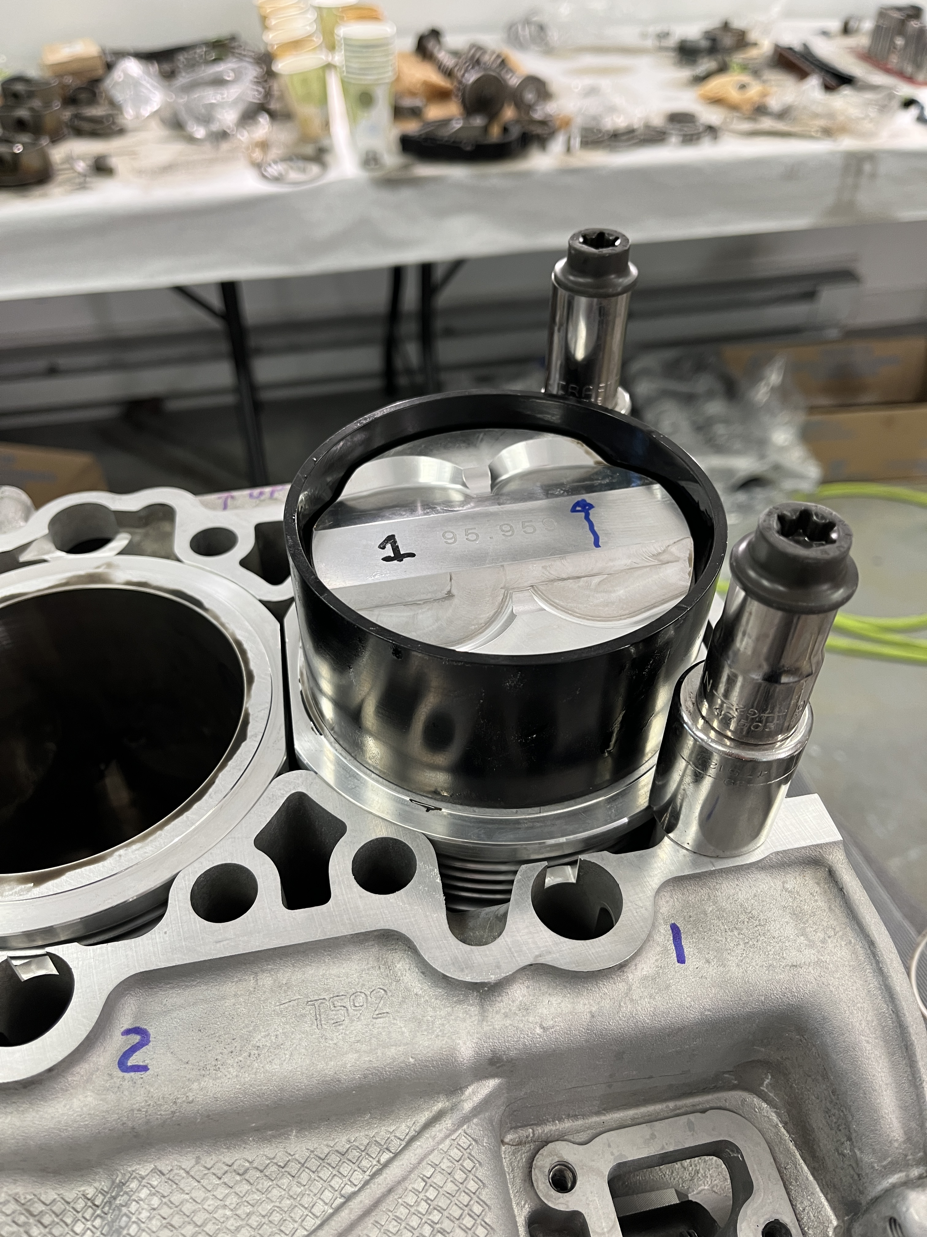
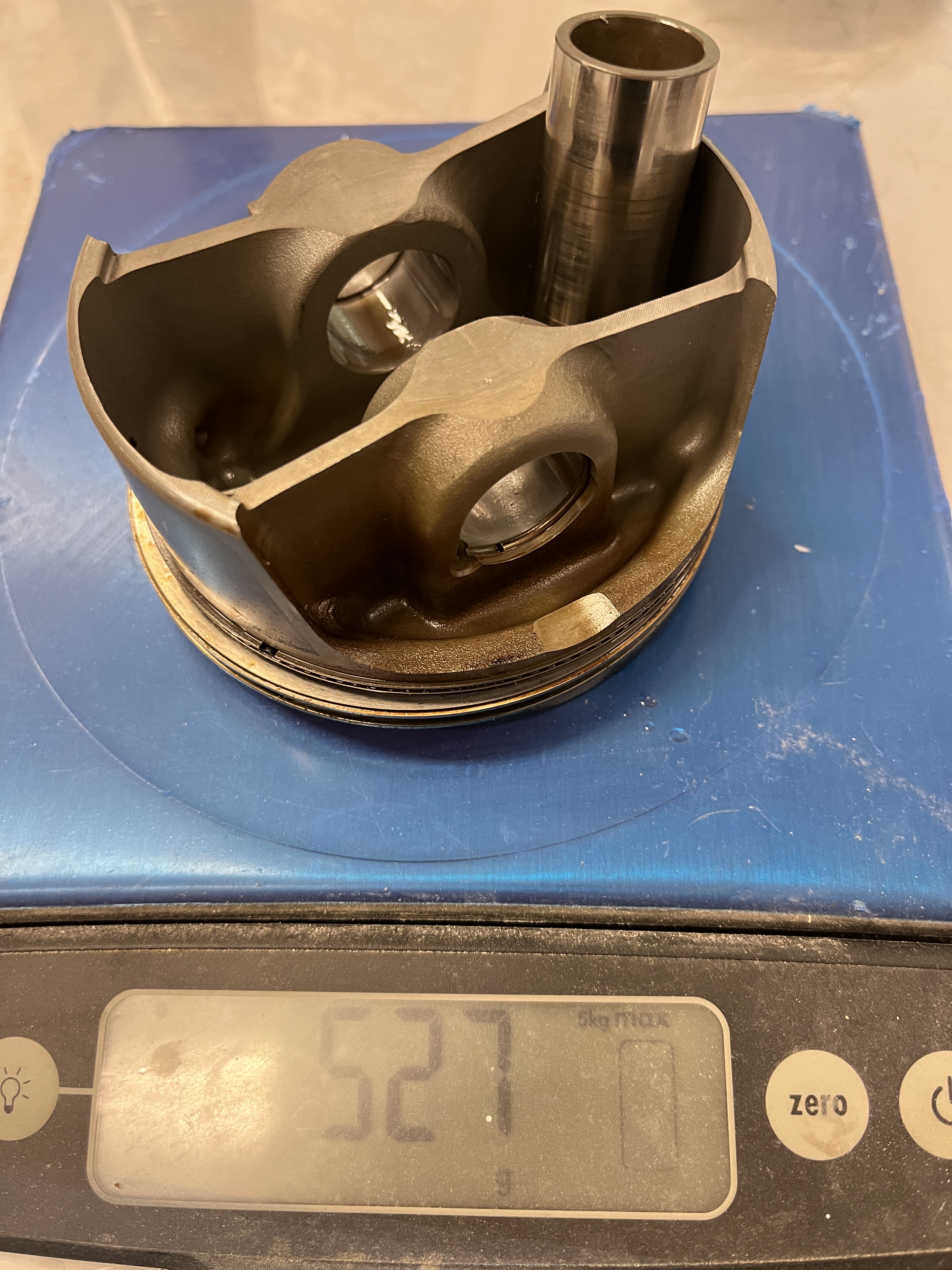
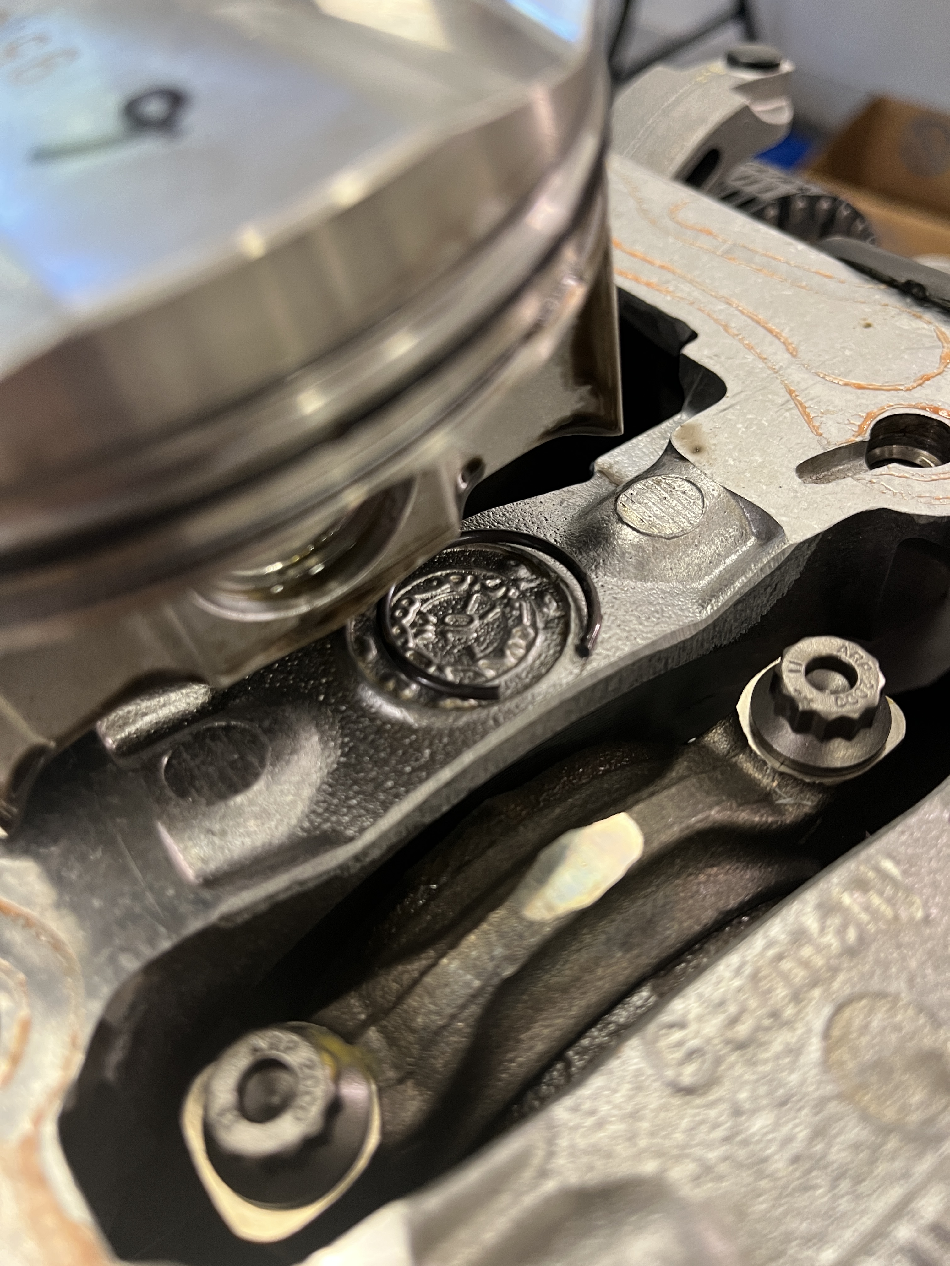
- Fitting piston pin circlips. Jake’s video does a good job of explaining how to use the factory tool to load and install a piston pin circlip into a piston. In his discussion, he is using a piston with a counterbore at the piston pin hole, where the tool is engaged and centered. I noted that the proprietary Hartech pistons only have a counterbore on one side, just like the factory pistons. On the side without a counterbore, the factory tool will not work directly. I scratched my head over this but the light bulb finally came only. Insertion is similar to that used with the factory tool. Instead of squeezing the circlip into the opening of the insertion tube, roughly perpendicular to its final orientation, you squeeze the circlip into the opening in the side of the piston, using your fingers. It takes some force! The clip will of course be rotated in the hole. Then you use the rod of the insertion tool, which is sized to fit inside the piston pin hole, to gradually rotate the circlip until it lines up and snaps into the groove. I wound up inserting the rod several times from both sides as required to rotate the circlip into position. As an aside, on bank 2, where you will be using the piston pin and circlip insertion tool through the small access openings in the block, installing the pistons in their proper “up” position will place the counterbore on the correct side. For the Hartech pistons, “up” is simply with the large etched size designations facing up. Be careful to check your work because if you get this backward you won’t be able to install the piston pin circlips.
- Fitting the rings. Do this pretty much as Jake describes. The top two rings that I received with the Hartech pistons had an “N” on the top side. The 2nd ring also has a relief or bevel that must face down. I checked the top rings in the cylinder bores for end gap. At the time of my installation, Hartech recommended 0.004” of clearance per inch of bore diameter, +/- 0.001”. For the 3 ¾” nominal bore of the 3.4L engine, that came out to 0.015”. All of mine were perfect. Remember, all of this will be different for you guys going with the larger displacement parts.
- Installing the pistons. Jake does a good job of explaining this. A couple of things. I used the ring compressor that is basically a tapered tube. I think this is vastly superior versus the ones that are adjustable. Make sure you get the taper going in the right direction. I had a brain fart and had it upside down. Fortunately I caught this before any harm was done. Another thing to watch out for is your rod bearing shell moving around. You install the rod bearings into the rod halves prior to installation, where they are held by friction. In my case, I lubed the bearings with the Hartech lubricant. On several of my bank 1 pistons, the bearings came loose or rotated. This is probably due to the fact that when the lubricated side of the bearing shell lands on the crankshaft journal, it wants to stick to the journal rather than remain engaged to the rod end. As you rotate the crank to get the journal at BDC, it can pull the bearing shell out of position. If this happens it is not the end of the world, since when you get things rotated to BDC you can reach in from the bottom and reposition them. But be sure and rotate the piston to bottom dead center where you can get your eyes on the bearings before installing the caps! BTW, I used the special wider width Hartech rod bearings.
- Installing the wrist pin circlips. Again, Jake does a good job of explaining this. That said, I had several “failures”. Three times, the circlip did not fully engage. More specifically, the circlip was determined visually to be in the counter bore area where the insertion guide tool is supposed to engage. The first time this happened, I tested out a hook to extract the clip. Suddenly the clip was gone. Damn! Reluctantly, I broke the case halves apart. I found the clip lying on the top of the crankshaft carrier. I cleaned everything up and re-assembled the case halves. The same thing happened again i.e. the clip was located in the counterbore. This time I purchased a ½” diameter wood dowel, which is small enough to fit inside the bore of the wrist pin but large enough to hold the clip from falling through. I was able to get the clip out. After some investigation, I determined that the plastic stop on the Porsche factory insertion tool did not allow full insertion of the tool into the counterbore in the piston. I used my lathe to remove about a ¼” of the plastic stop. I also purchased some right angle mirrors for my endoscope. This time I was able to confirm full insertion of the tool and the pin inserted correctly into its groove. Feeling confident I moved on to piston 5. The same thing happened again. This time I made further inspections and determined that the insertion tool was not fully seating in the counterbore. WTF! I had to add a chamfer to the end of the tool, which apparently overcame some misalignment and allowed the tool to fully seat. This time the clip engaged correctly. By the time I got to piston 4, I had the process down and things went smoothly. The visual quality of the right angle mirrors is commensurate with their low cost. If you can get a endoscope with a decent side view capability, do so!
- Micro Encapsulated Bolts. In several instances the Porsche shop manual calls for micro encapsulated bolts. When new, these are fairly obvious as they have a blue paste on a portion of the threads. This paste is basically a chemical thread locker, just like traditional Loctite Blue or Red. Folks argue that Loctite Blue can be used on your old bolts and I don’t disagree. Just maintain an awareness of which bolts were assembled at the factory with micro encapsulation and be sure and treat the same ones with Loctite blue. Be aware that some bolts have encapsulant under the bolt head, which I suspect is there to keep fluid from leaking out from the joint. Since there aren’t that many of these in the great scheme of things, I found the cost of buying OEM encapsulated bolts from Porsche was not too bad.
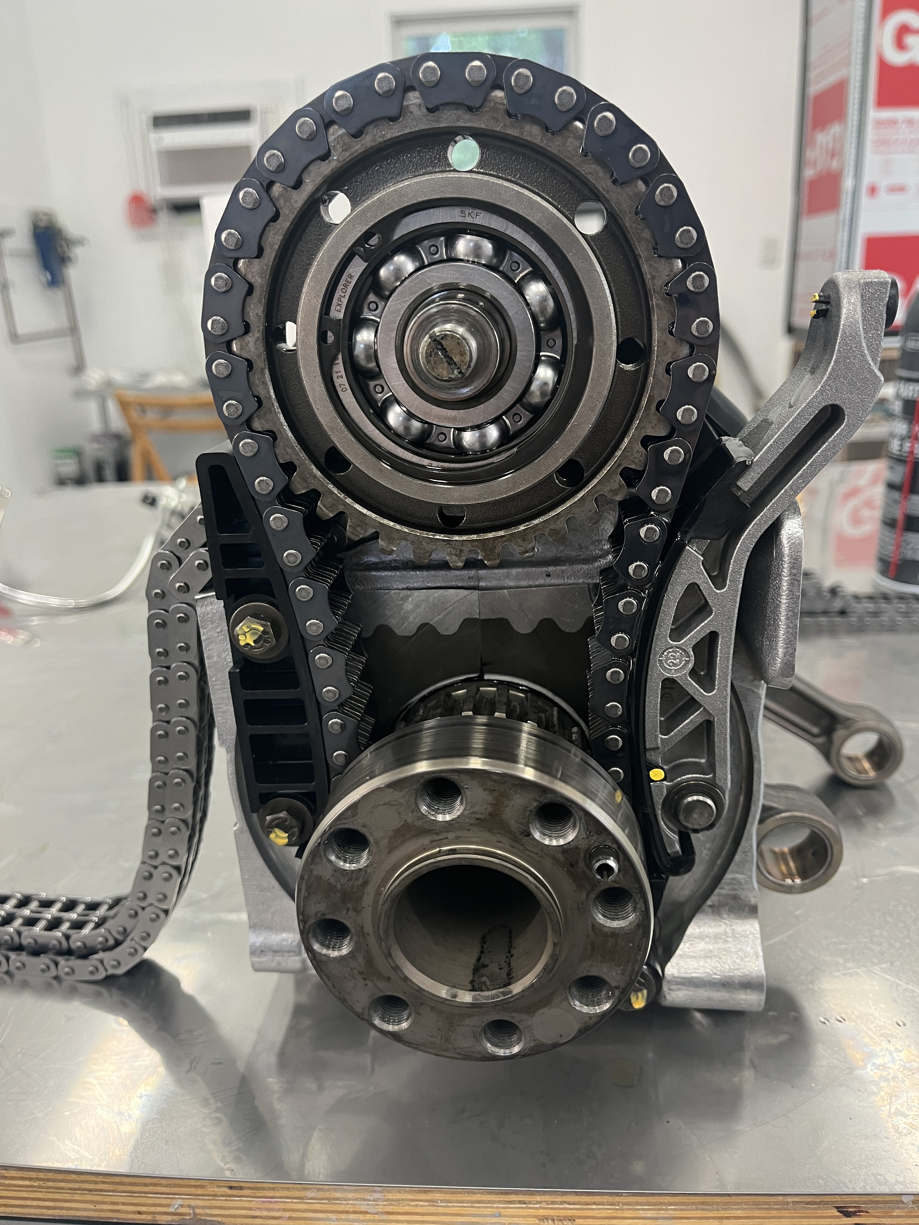
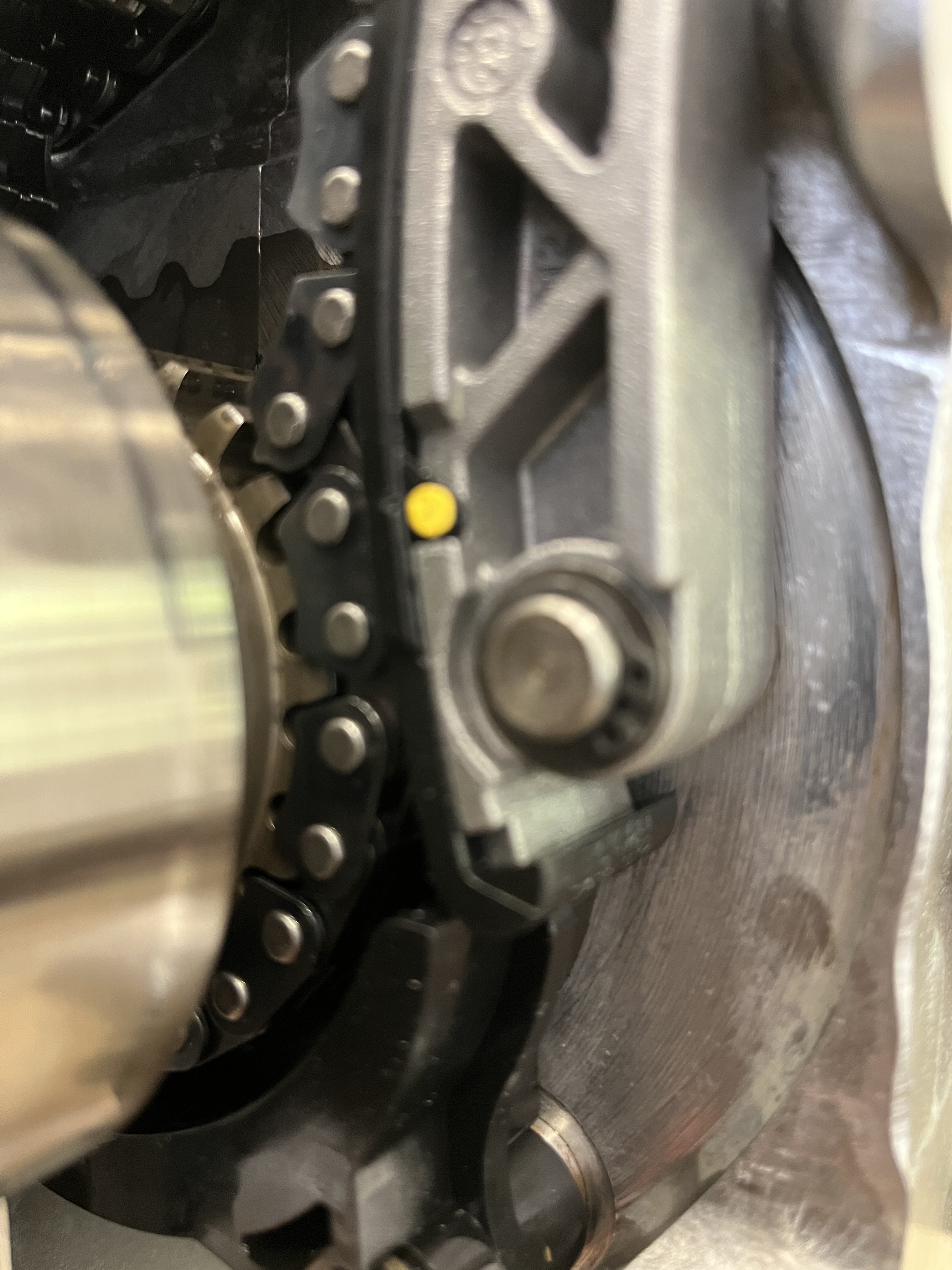
- Short timing change alignment. This issue was brought to my attention by Brandon at SRD. The “short timing chain” is the one that goes from the crankshaft gear to the intermediate shaft gear. For reasons that are not obvious, when you install the timing chain tensioner blade (996 105 165 55), you may upset the fitment of the chain on the crank pulley such that it is a half tooth off. It happened to me. Once you see what is going on, you can remove the circlip and washer that holds on the tensioner blade and then reposition the chain. Make this check right before you install the bank 2 crankcase half. If the chain is mis-installed, you will not be able to center the IMS in the center of the opening in the crankcase and you will not be able to install the bearing retainer.
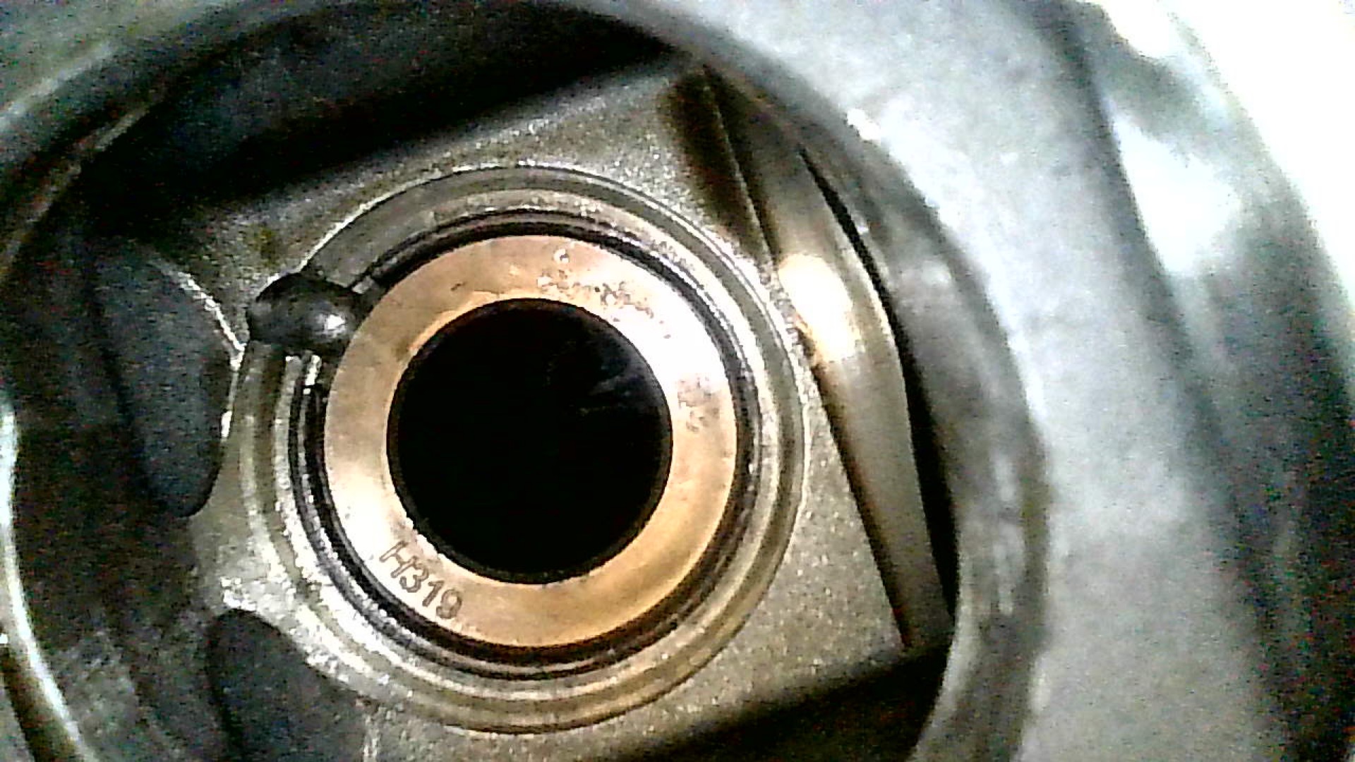
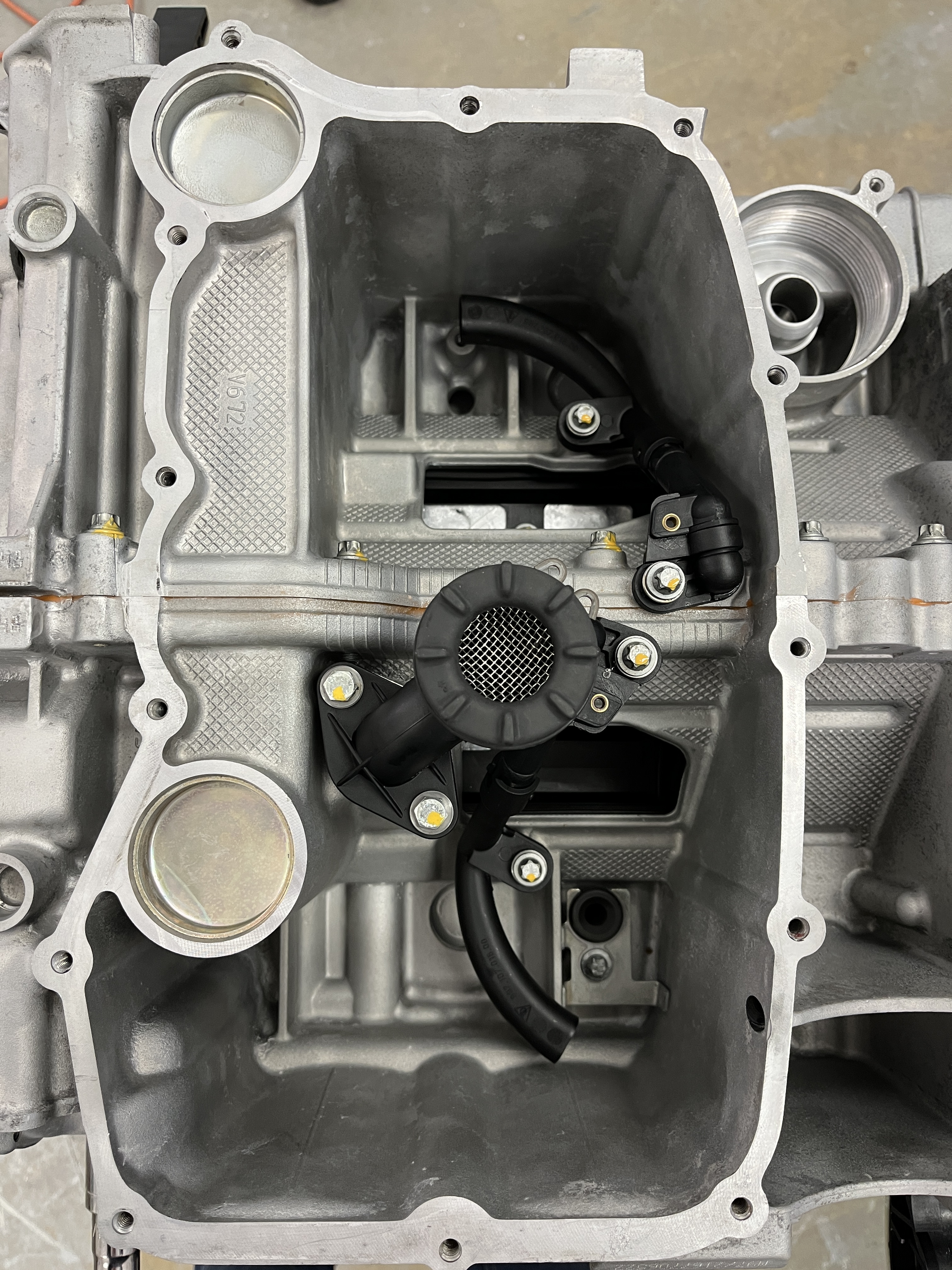
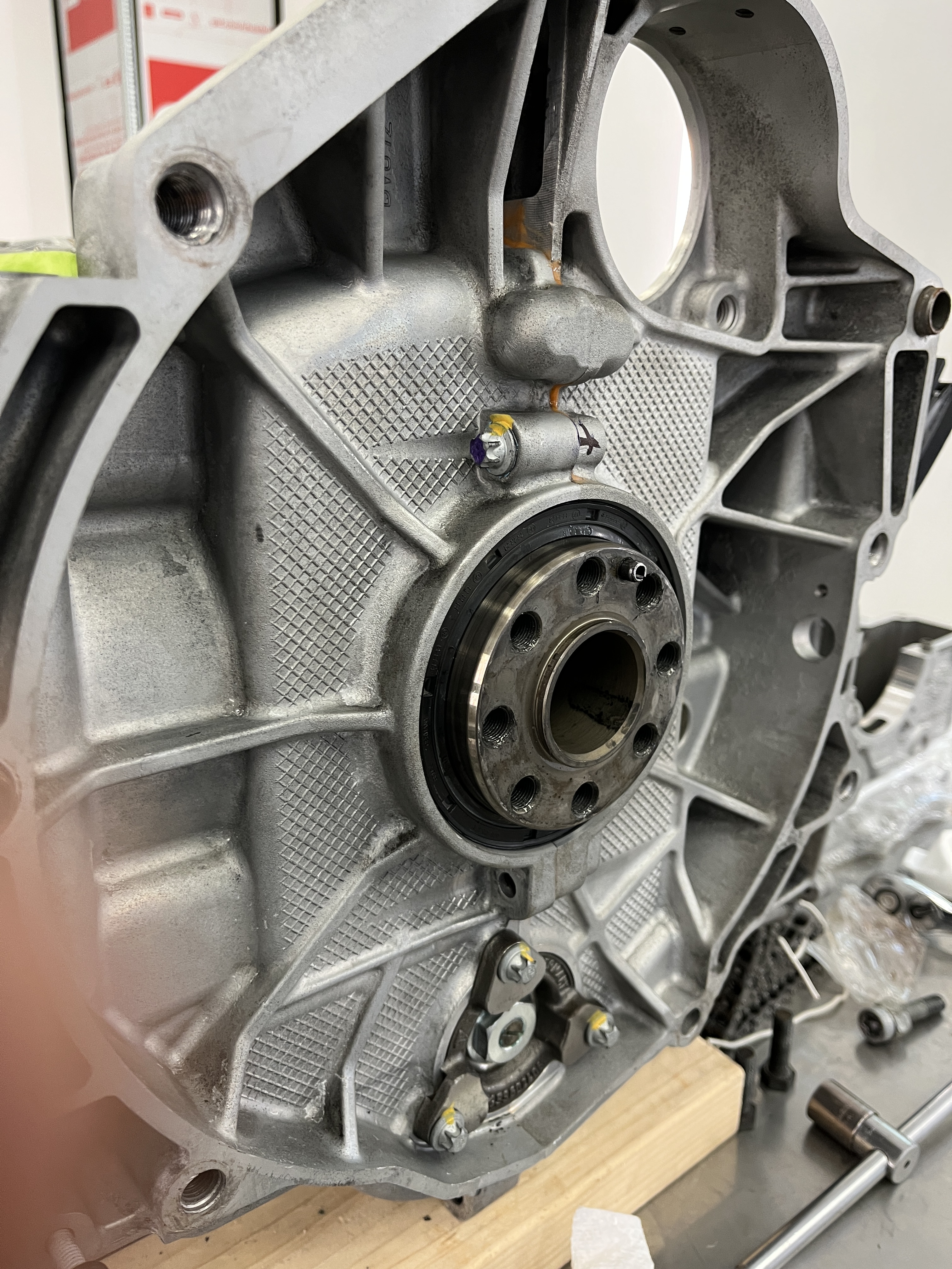
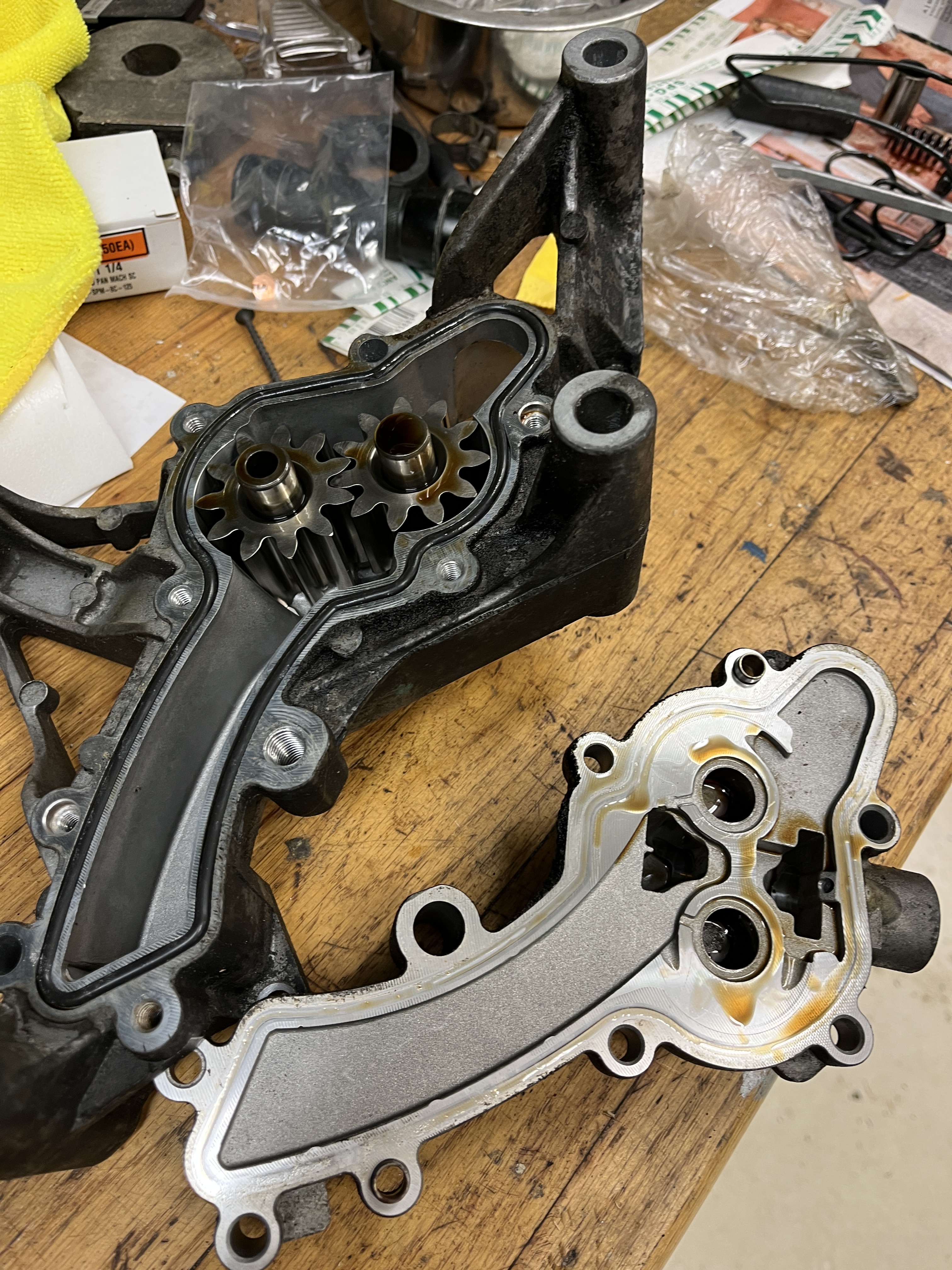
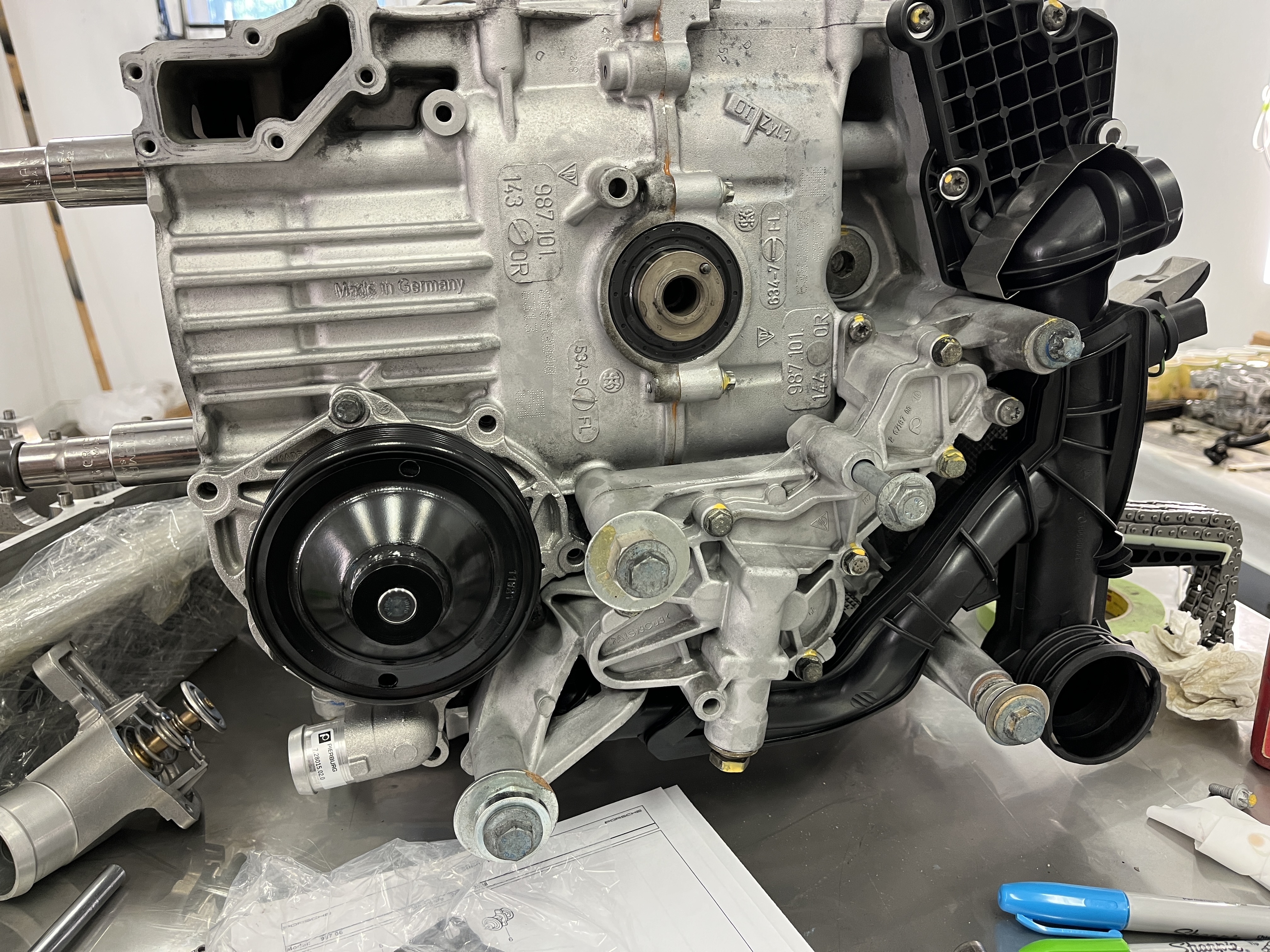
- Installing the front and rear components. As Jake describes, after the bank 2 pistons are installed it is a good time to install the front and rear mainshaft seals, the IMS front bearing retainer, the rear IMS/oil pump console, the water distribution console, the water pump, and the thermostat. The large PTFE rear mainshaft seal is a little finicky to insert straight but careful tightening of the tool brings it home. Insert to the 13 mm depth below the flywheel flange as per the shop manual. I used the LN Engineering insertion tool. Once you get it partially installed, you remove the tool and take out the blue plastic protection device, then reinstall the tool and proceed to the 13 mm depth.
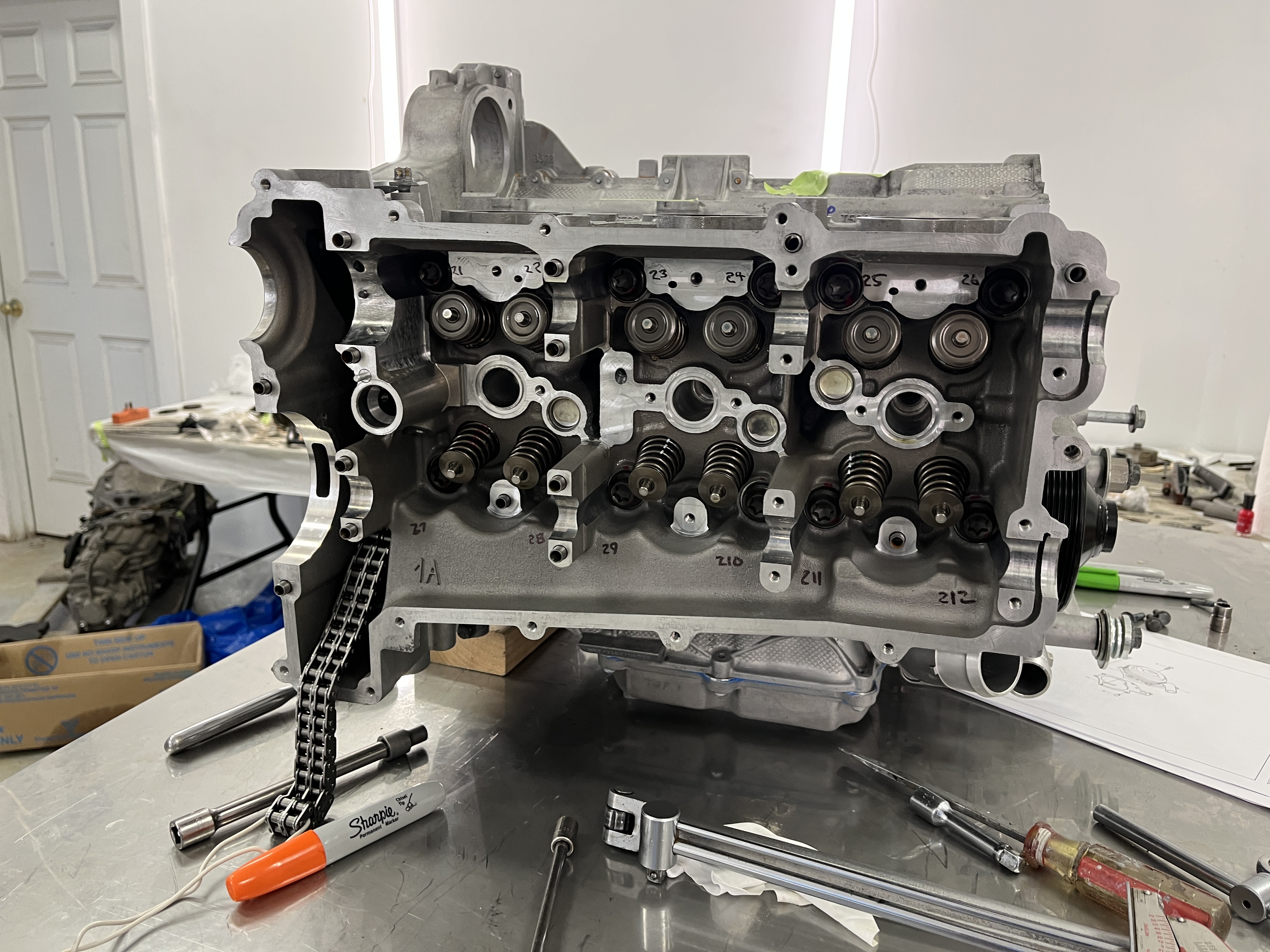
- Installing the cylinder heads. No real drama here. Use the process that Jake describes and you should be good to go. I used Loctite 574 to seal the area Jake denotes around the opening for the timing chains. As an aside, I measured the length of the “torque to yield” cylinder head bolts. The used ones were about .040” longer than the new ones. So that gives you an idea of how much they stretch.
At this point in the process, I had to leave for 10 days to babysit my grandchildren in Seattle. Not a bad gig, as they are in school during the day. I decided to post this article, Part 1, while I had the time to write it. From here forward, I will of course be installing the camshafts and the timing chains, and the valve covers. From there, the basic block will be completed and I will start adding on all the ancillary components.
Now, lots of pictures!


Discussion
Comments are closed.