I bet you are thinking “Wow, Newhillgarage is really running out of ideas for content” And at some level you are right. After the excitement of installing the engine, lesser topics are going to pale in comparison. But bear with me, as I bet the floors on an Etype are something you rarely get to see and you might be surprised at what you have been missing.
Let’s start with the area in front of the seats. You may have heard of “flat floor” Etypes. The earliest cars did indeed have flat floors. Feedback from real world drivers indicated that things were pretty cramped in the footwells. A solution was to insert a dropped or lower section into the floorboards to create more room. All Etypes after the first year of production have footwells. The footwells are a low point and collect water and thus rust. My car threw me a curveball in that the footwells were not rusted but upon closer inspection, they had been replaced at some point. With garden variety 1/8″ thick flat plate. The installation was very stout but not at all factory original. One of my first projects on this car was to cut out the footwells and replace them with properly formed reproduction items from SNG. Why bother? No, the floors don’t get judged in a concours but the footwells I had screamed “bodge”. The had to go. Actually, the bulkheads at the forward ends of the footwells had received the same treatment. All of this was cut out and replaced with panels accurate to the factory original patterns.


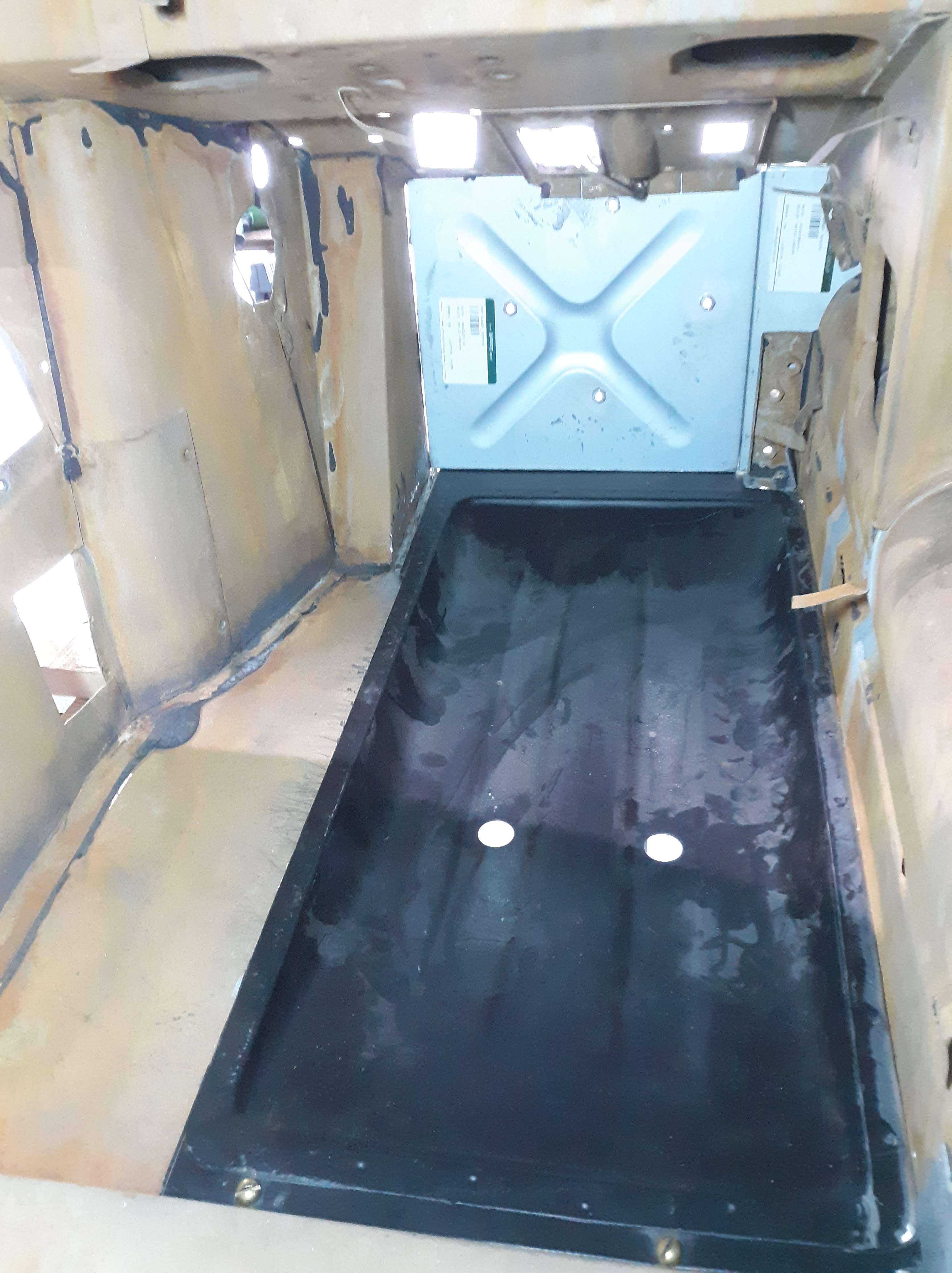
In this picture you can see the replacement parts. Both have been die forged with a distinctive pattern of stiffening webs that the flat plates don’t have. Those two holes seem to be drain holes, as they are located at the lowest point. Here they are nicely painted.
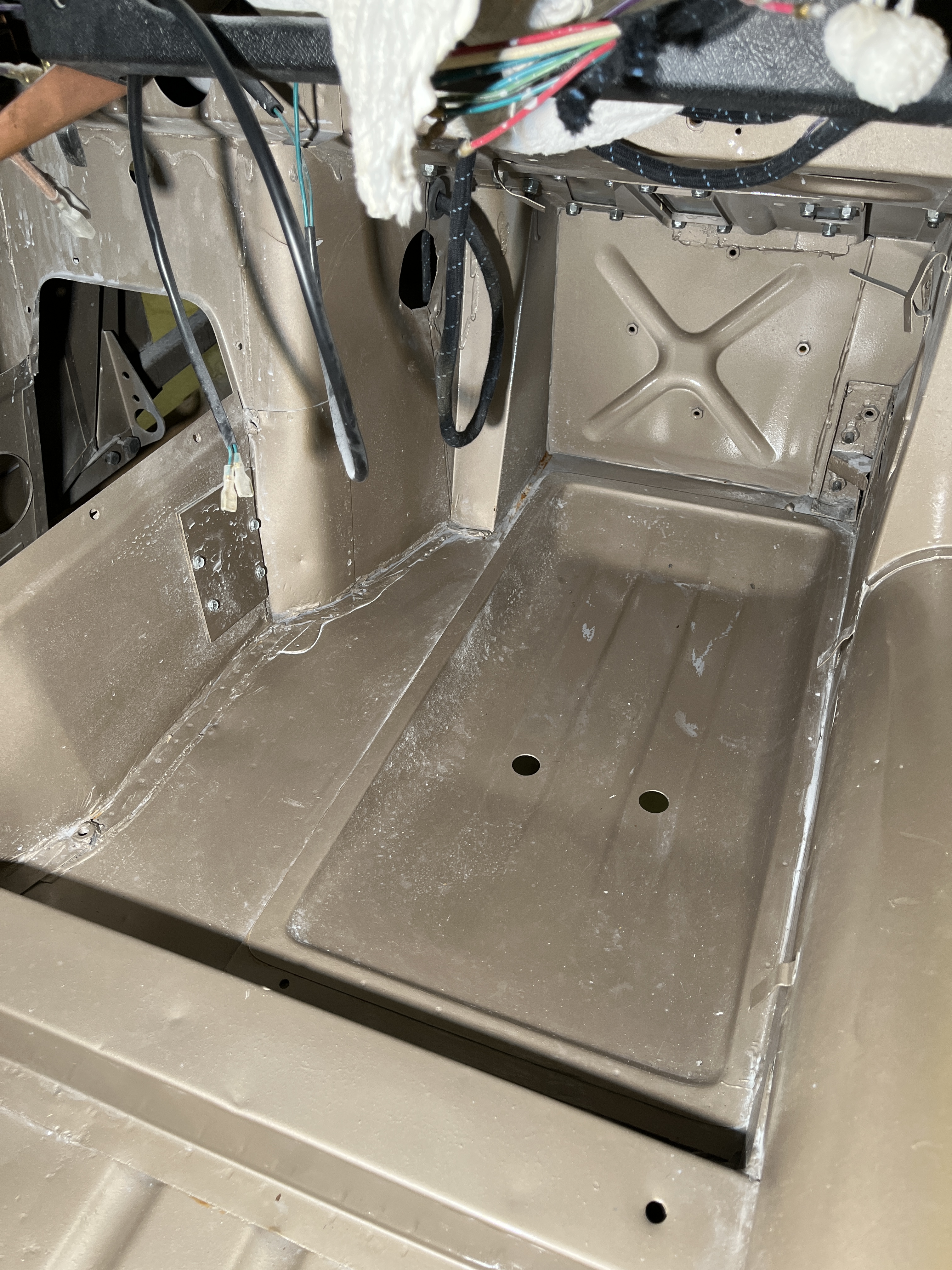


So that is about it for the front floors. There are two small holes, just barely visible in the shadow area of the above photos, that are for plastic female plugs that receive a male plug inserted in the floor board carpet, to keep it from sliding forward.
An area that you probably rarely see is under and behind the seats. This area was sound and rust free. It had more holes but as we will see, they all served a purpose.
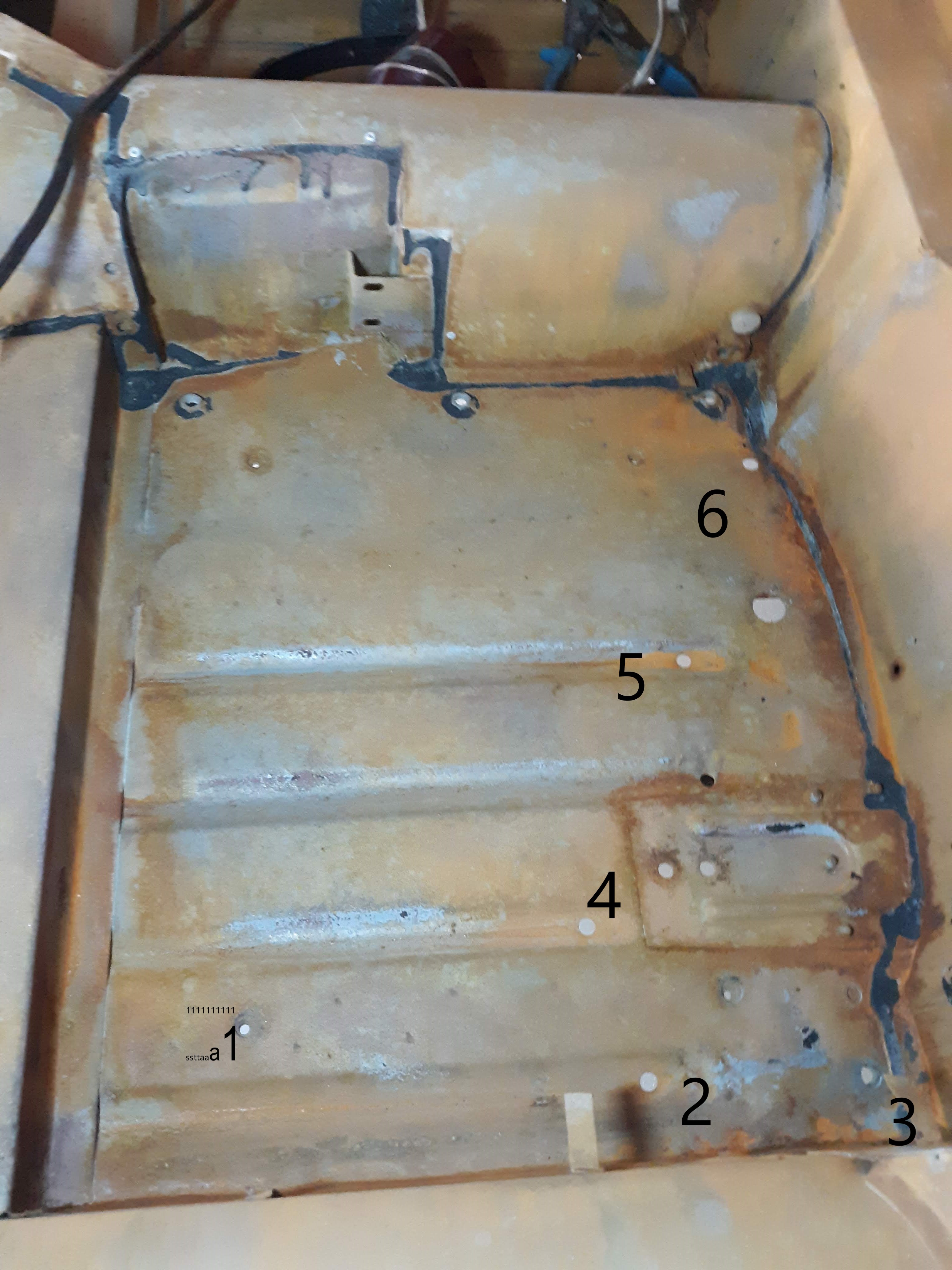
Here is a picture I took of my original floors. I added the numbers prior to sending it to an expert to help identify all the holes. Here is what I found
1. This is the front hole for mounting the seat rail. The rear hole is just above the number 2. There are two more matching holes up in the vicinity of 6. They have 5/16″ UNF welded captive nuts.
2, 4, & 5. These are apparantly drain holes, as they reside at the aft end of the shallow depression that serves as a stiffening element to the floor.
3. A tapped hole for the seat belt anchorage.
To the right of 4, there are two closely spaced holes. These are for the bolts that attach the front end of the radius arm safety bracket.
Down and to the right from 6 is a large hole. There was some educated speculation put forth on Jag-Lovers that this hole was used to locate the panel on the assembly jig prior to welding. Sounds good to me as I never found a use for it.
Up near the top of the photo are 3 holes in a row. It turns out these were not factory but had been added by someone. I used them to attach the heat shield underneath between the floor and center mufflers.
In the upper right hand side of the picture there is a threaded bung up on the side of the tunnel. This is for a seat belt attachment. In the top middle of the picture are two holes in a bracket that attach the parking brake. And all that black goop is the factory seam sealer.
So as you can see, there are a lot of holes in this area. Now I’ll give you some progress pictures to show how everything came together.


In this picture, everything is loosely installed. The seat runners sit on “distance pieces” to hold them in a solid manner above the squishy Hardura mat. I decided to not use the seat belt mount on the tunnel, instead I installed a nut plate underneath the floor. Mostly because my OCD wanted the seat belt mounts to be symetrical!

Lastly, let’s look at the boot floors. Fortunately, these were sound and rust free on my car, as they are quite involved to replace.


Key details in the picture that you can see are the cicular mounting point for the spare tire, the large round opening for the fuel tank drain, center left is the opening for the backup lamp, various stiffener elements, and random holes at the low point of the boot. Again, I surmise these were meant to be drain holes. BTW, I put solid rubber grommets in all the drain holes. Unlike maybe as on a Boston Whaler boat, I did not feel that a self bailing feature would be neccesary in this show car’s future!
So that is about it for my tour of the floors. I bet you learned something, right?

Discussion
Comments are closed.