One relatively simple task that I recently completed was the refurbishment of the steering column. The steering columns main job is to connect your steering wheel to your steering rack. Things get a little more interesting when you introduce turn signal and horn functions. So let’s get into it.
The first thing I did was find the long rod that goes from the steering rack up through the firewall into the cockpit. There is nothing special here. It is about 3/4″ in diameter and has splines at both ends that accept small universal joints (U-joints). I purchased new U-joint “spider” bearings from SNG. These are similar to the U-joints on your driveshaft. One thing that surprised me is that there does not seem to be a way to press out the old spider bearing. I cut it into pieces with a wafer disc. Once I had the constituent parts dis-assembled, everything got a bead blast and a coat of rattle can black paint. The new spider bearings can be pressed into place with a vice. I had previously detailed the accelerator pedal box mounted on the exterior of the firewall. It has a opening with a grommet through which the shaft passes. After you get the shaft inserted, the upper U-joint is installed. I am deferring installation of the shaft until I install the engine, just be make sure there are no interferences.


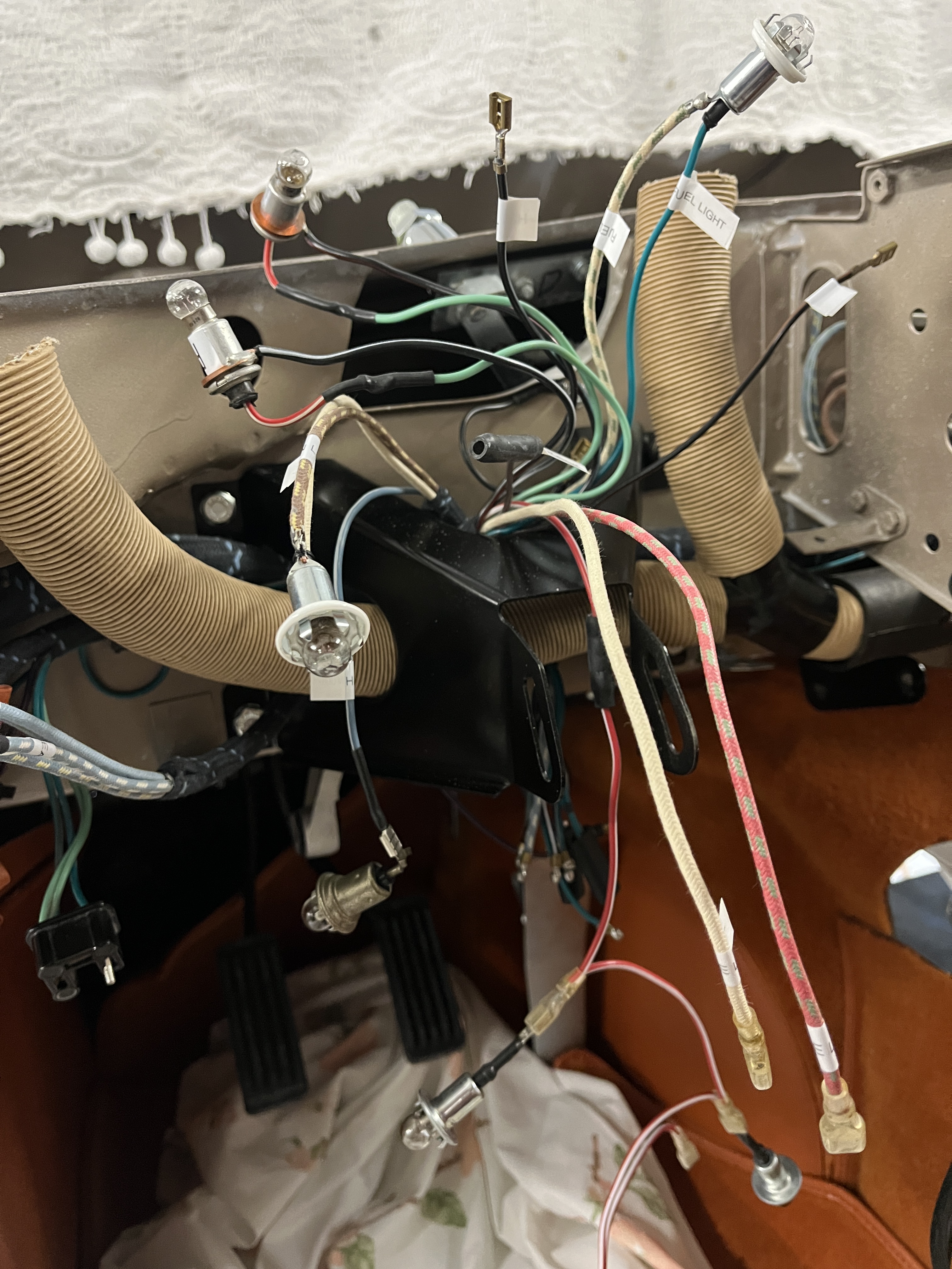
That was the easy part! Next I dis-assembled the steering column and it’s support bracket. The support bracket got a bead blast and paint. It is now installed in the inside of the dash. As you can see from the picture, demister tubes and wiring harnesses pass through it so you want to get it into position sooner rather than later.
I dis-assembled the steering column. Take pictures! First off was the turn signal mechanism and the adjuster for the extendable steering wheel shaft. I took enough of the horn electrical contacts off to establish that those left in place were functional. Then I gave everything a bead blast and paint.
Many folks are perplexed as to how the horn works. It is a little wonky but remember, you are having to transmit an electrical signal from a shaft that turns to one that is stationary. The SPC actually shows it pretty well, once you have the actual parts in front of you. The harness wire for the horn connects to the female bullet connector shown in the photo below.
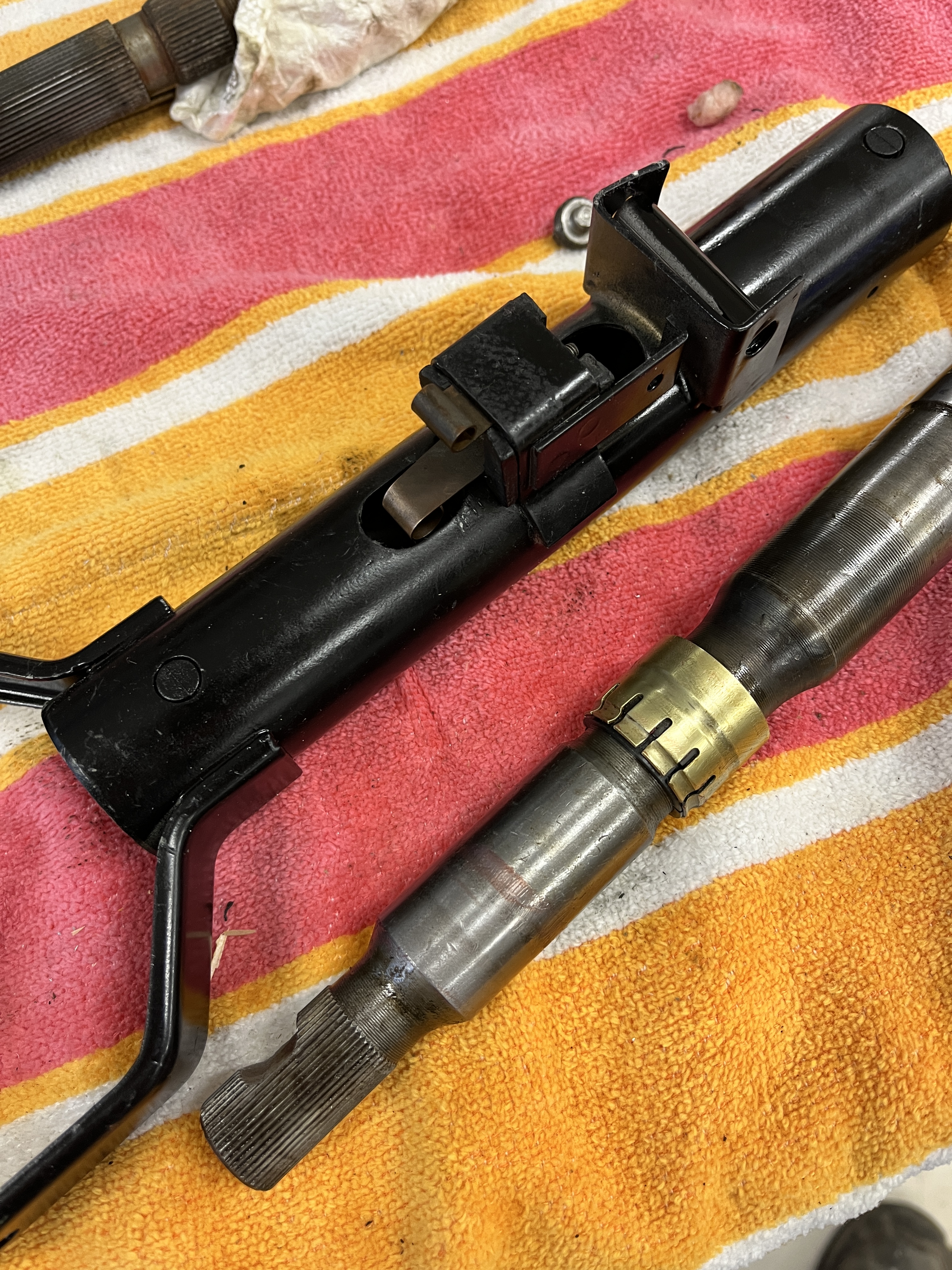
Looking at the above picture, the brass piece on the shaft that turns is mounted on a non-conducting sleeve. The dull brown piece on the housing is also mounted in non-conducting materials. It sticks through the hole in the housing and “wipes” on the brass piece, generating an electrical connection that rotates with the shaft.
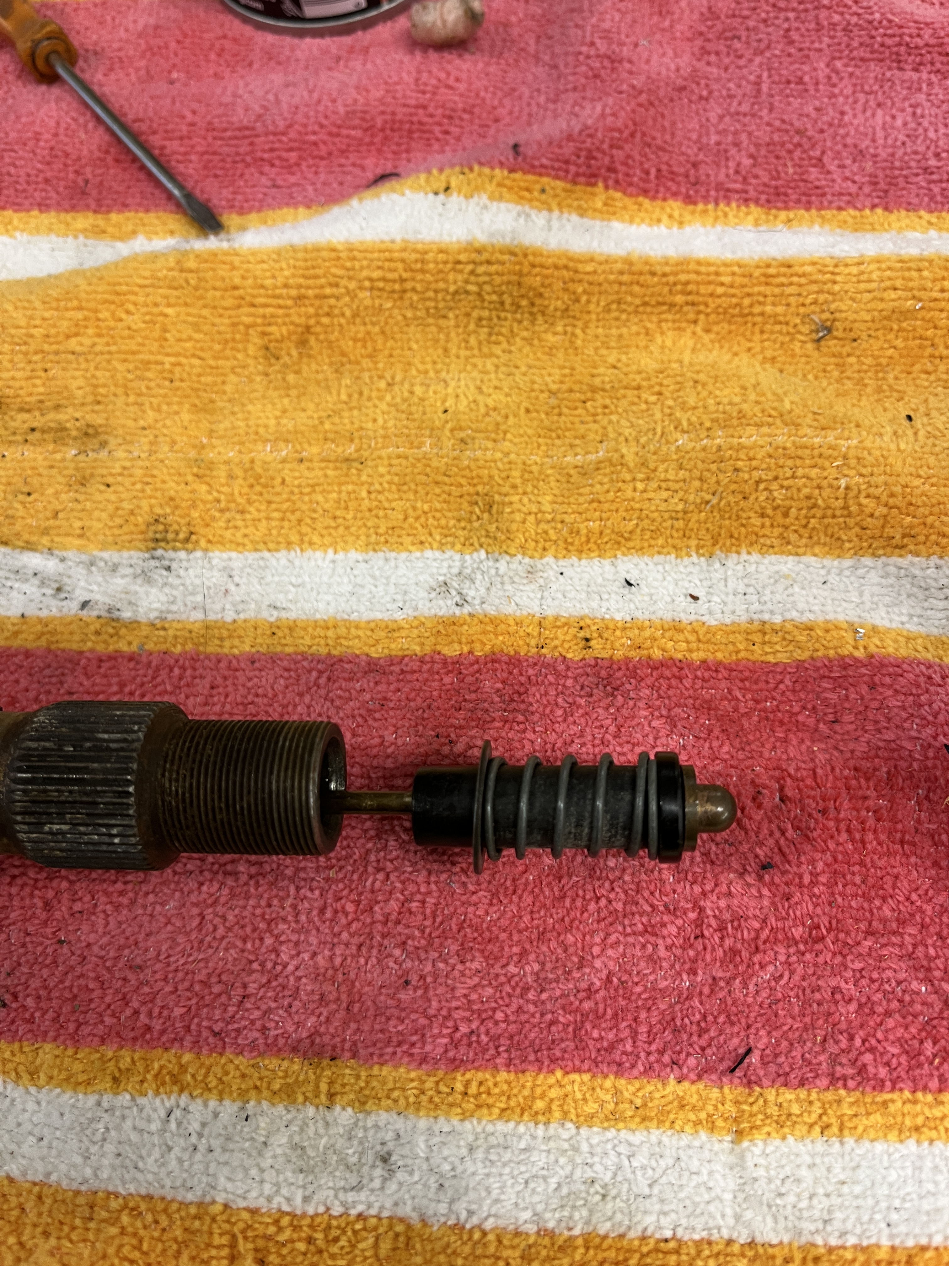
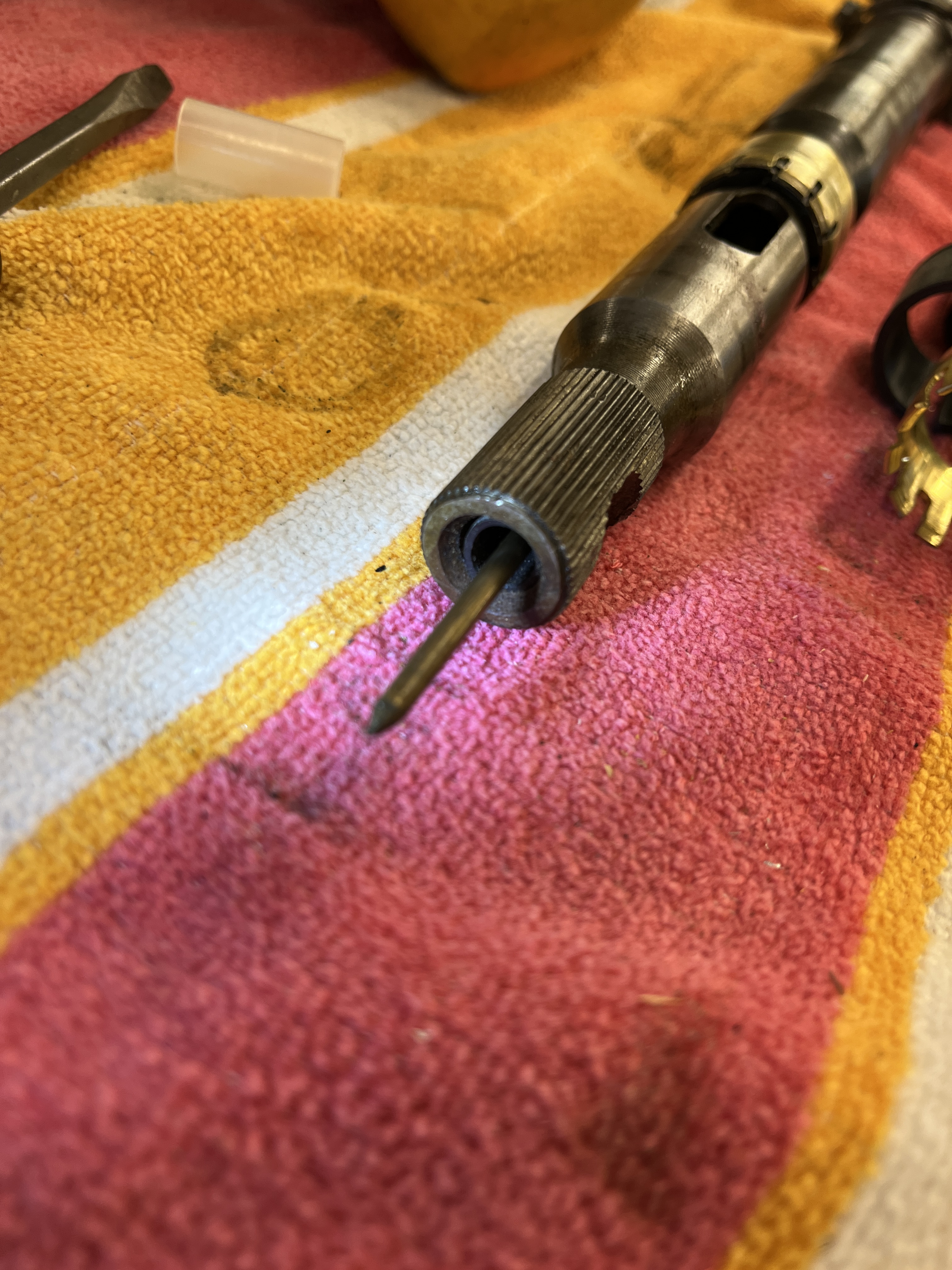
What I cannot show you, because I didn’t need to take it apart, is that under the brass piece is another short brass pin that extends through to the center of the shaft. It is spring loaded. It wipes on the thin rod that extends down the center of the shaft. This rod inserts from the outer end of the shaft. As you insert the rod, you will feel some resistance as it encounters the spring loaded pin. When the parts are in good shape, the rod pushes past the pin and engages another non-conducting sleeve at the lower end of the shaft. It is also held at its outer end with a non-conductiong sleeve. This rod contacts the horn push button and completes an electrical circuit, sounding the horn.

All of these pieces come in a horn repair cut from SNG, shown above. As it turned out, I didn’t need any of them. You can test the above described function with a meter and determine if you have a problem with these parts or elsewhere. BTW, the original design has the shaft supported with fibrous sleeves. I replaced these with poly sleeves I purchased from SNG.
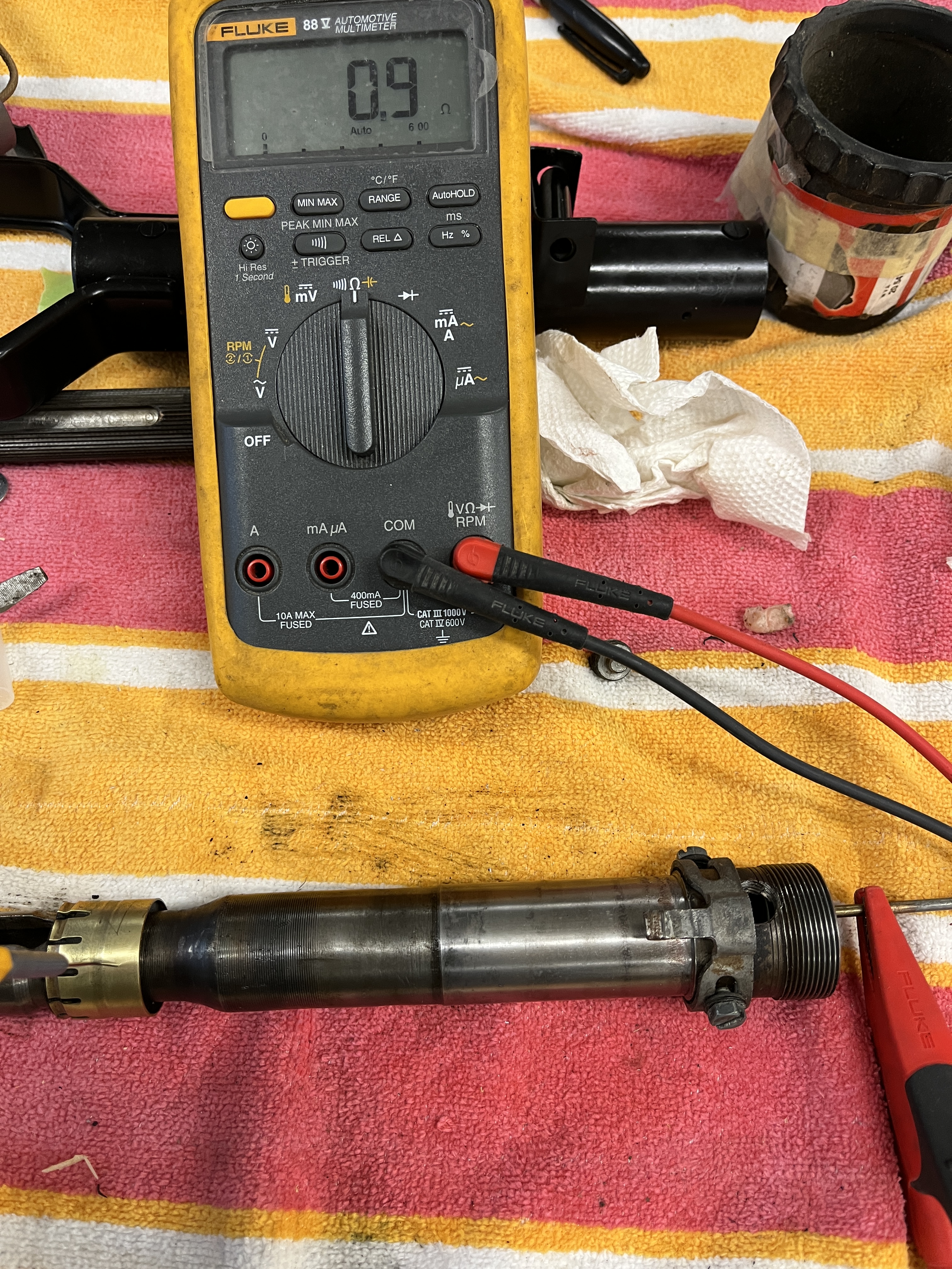
Next I moved on to the turn signal indicator. BTW, in the above picture, the odd shaped piece to the left of the red meter clamp serves to “cancel” the turn signals. It is adjustable in its position. I removed the turn signal indicator and using a test meter and the factory wiring diagram, I tested all the key electrical functions. This was after cleaning it liberally with DeOxit. It seemed to be working fine. I did find that the chrome on the stalk was perished. Fortunately, SNG was able to sell me just the stalk. I painted the cover pieces and reassembled everything. The green tape is holding two special half shell shims that need to be in place when you install your steering wheel.


Re-assembled and looking sharp. Another small job I can put on the shelf awaiting final assembly.

Discussion
Comments are closed.