A major part of the allure of a Porsche 944 is its very balanced suspension setup. The designers at Porsche moved the normal position of the transmission from just behind the engine to a location roughly in line with the rear axle. The combination of a transmission and a differential is commonly called a “transaxle”. The beneficial result is that the total weight of the car is almost perfectly split between the front and rear axles. This is commonly referred to as a 50:50 weight distribution.
The cornering power of any car can roughly be determined as the sum of the grip of each of the 4 tires. The lateral grip of a tire is a function of many factors such as the tire compound, the road surface characteristics, and the load on the tire. As the downward force on the tire increases, the lateral grip increases. Up to a point. If the weight increases too much, the tire is overloaded and quickly looses max grip and then begins to slide. In a corner, the weight of the car is shifted to the 2 outside tires. The best cornering power can be obtained when both the front and rear outside tires add load at an equal rate. They both reach their maximum grip at the same time and the car corners the best.
This is obviously a simplification. Vast time, thought, and money is spent in motorsport to obtain the best cornering out of a car. I have spent a lot of time reading about suspension design and feel that I have a pretty good understanding of the basic principles. So I like to try things out on my track car to make it faster in the corners. (Being a normally aspirated 944 there isn’t much I can do about the straight line part!) My track car is lowered, has stiffer springs, torsion bars, and roll bars, and has aggressive shock absorbers. And it has gone through a massive weight loss program. All of this coupled with R-Comp track tires make it a very fun car to drive on track.
As part of my track car development, I have come up with an Excel spreadsheet that compiles the various math equations required to predict the performance of various suspension modifications. The spreadsheet is based heavily on the book by Stanisforth, as reviewed here. Starting with input values that can be measured or estimated from the car, the equations can be applied to predict the effect of suspension changes on the cars cornering performance. My goal is to optimize the cornering power with a minimum of trial and error. Not always achievable but that is the goal. Here is sheet 1 of the spreadsheet.

Suspension Spreadsheet Sh. 1
As you can see, you won’t get very far unless you have access to some scales. I purchased my scales from Longacre a few years ago and have used them a lot. Due to the weights involved, I don’t believe bathroom type scales would cut it, although I’m sure someone somewhere has figured out a way to use them and save some money. I am proud to announce that the weight loss plan for 944 street/track car resulted in a dry weight just under 2500 pounds. This did not include any fuel, the radiator was dry, and the spare tire removed. But in general, you’ll want to check your suspension weights with all fluids, including at least 1/3 of a tank of fuel. The driver also adds weight but I tend to check the car without the driver, because it tends to be a hassle and it is near the fore/aft center of gravity of the car, where its effect is less significant.

Car weight = 2498 pounds!
So once you have the car on the scales, obtaining the weight on the front and rear axles is very simple. Getting the unsprung weight (the weight of the car that is not supported by the springs) is a little tougher. If you have the suspension torn apart, you can weigh the individual components. It is certainly easy to take the tire/wheel off and weight it. What I did is shown in the following photo. This only works if the springs and the torsion bars are not engaged. I would say that if you were to take off the rotor and disc brake caliper and weigh those and add them to the tire weight, you would be pretty close.
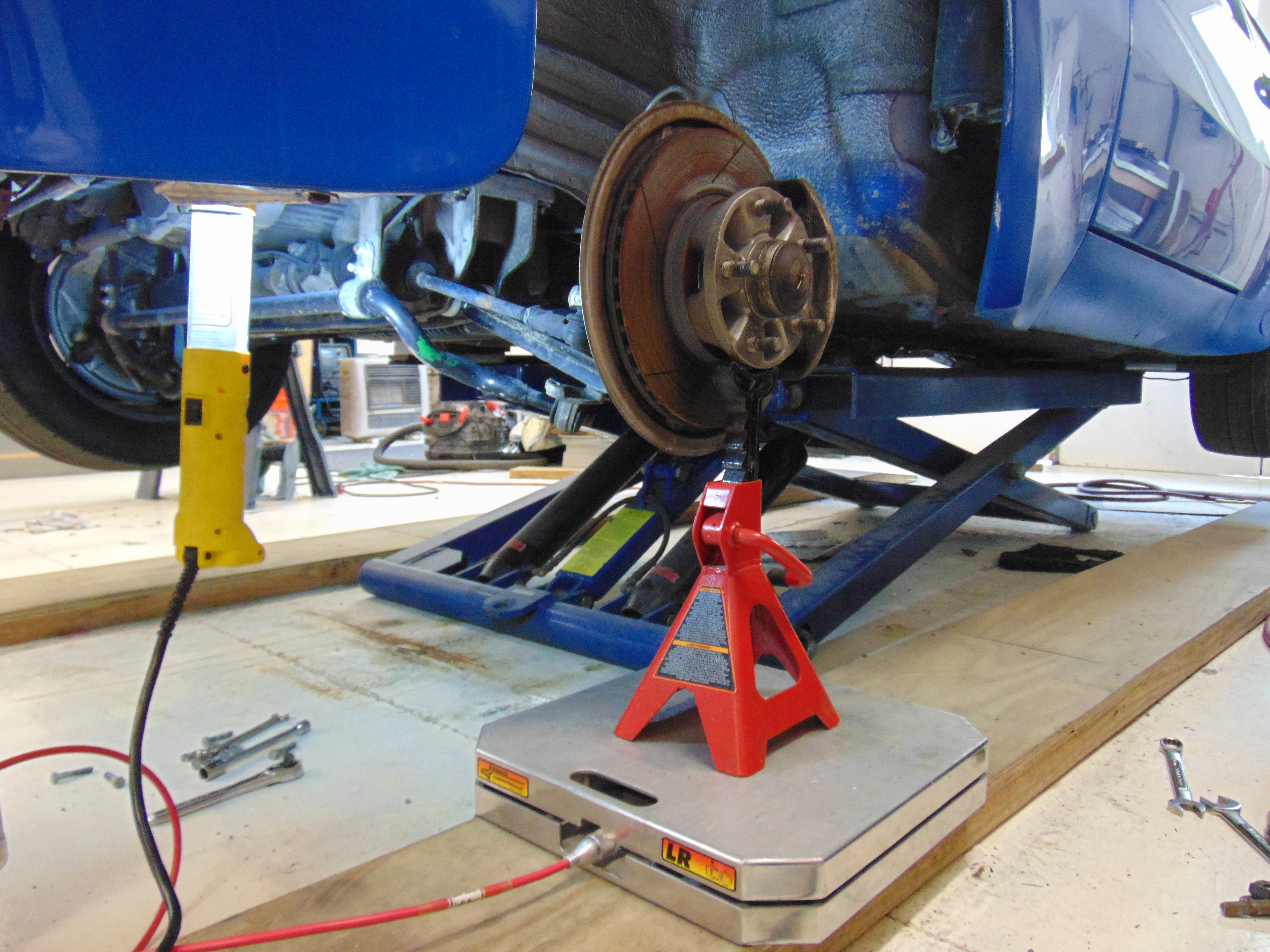
Checking unsprung weight
Front and rear track width is a simple measurement with a tape. Measure to the middle of each tire. The height of the axles is basically 1/2 of the diameter of your tires. The next item on the spreadsheet is the roll center. This can be a complicated subject worthy of it’s own article. But if you check the internet for roll center on a McPherson strut car, you will find diagrams that explain it pretty well. You do need some angle measurements and some dimensions from the car. If you don’t lower your car and the A-arms are set up level, the diagrams are fairly simple. This car is lowered and thus the A-arms are inclined. This affects the roll center and it can be an adverse affect if you go too extreme on the lowering part. You don’t really want your roll center to be below the level of the ground. I measured my A-arm angles as shown in the following photo and established the roll center graphically by drawing out the suspension on a large sheet of paper. The angle measurements are easy if you have a digital level. I bought one for around $100 and use it a lot. It can also be used to check castor and camber.

Checking the angle of the A-arm
The final line item on the first page of the spreadsheet is the vertical center of gravity. There is a complicated way of checking the cg which involves lifting one end of the car substantially while you measure the weight shift on the other end. I have tried it. It seems dangerous and I had trouble getting results that I believed. So I made an educated guess that places the cg about 1/3 of the way up on the engine. Fortunately, this parameter is not super critical. It affects the calculated roll angle of the car, which is interesting but probably not too important in the great scheme of things.
With these values, the spreadsheet can calculate the gross weight transfer to the loaded side of the car. I have input a 1 “g” lateral acceleration. On my track car, which has some simple data collection, I typically reach a lateral loading of 1 g in many turns. It may seem counter intuitive but the total weight transfer to the loaded side of the car cannot be affected by the selection of springs or shock absorbers. What can be affected is the ratio of the weight transfer between the front and rear tires, by the selection of springs and roll bars. The dynamic or instantaneous rate of weight transfer is controlled by the shocks. So these components most definitely control how much roll the car incurs during cornering. My simple goal with spring and roll bar selection is to keep the weight transfer on the front and rear tires as equal as possible, so as to not overload a single tire and thus reduce total cornering power.

Spreadsheet Sheet 2
Spreadsheet Sheet 3
The remainder of the spreadsheet calculates whether your spring and roll bar selection will result in a balanced transfer of load to the front and rear of the car. If you get it wrong, your car will “push” i.e. exhibit understeer or it will be “loose” i.e. exhibit oversteer. Oversteer is when the rear of the car is trying to come around and kill you. Understeer is when the front of the car wants to push off the track and kill you. Both are to be avoided, although most passenger cars are set up with understeer, since it behaves more benignly as the throttle is lifted and the brakes applied.
There are a number of factors required to determine whether your load transfer is neutral, oversteer, or understeer. An obvious factor is the “spring rate” of the springs you have selected. In simple terms, spring rate is the amount of force the spring exerts on the scale for every inch it is compressed. So it is commonly referred to in “pounds/inch”. Some people leave off the inch part. A stock 1984 944 came with 175 pound/inch springs in the front. My build went with a modest increase of 200 lb/in. One advantage of these springs is that they are physically shorter and thus allow the car to be lowered a bit. The rear “springs” are a little trickier on a 944, as they are torsion bars. The math to compute the “spring rate” of the torsion bars is included in the spreadsheet. One needs to know the diameter of the torsion bar, its length, and the distance from the torsion bar to the rear hub. You can buy new torsion bars in various diameter up to 30 mm. The other two parameters are basically fixed by the design of the car. My build uses the stock torsion bars in the rear.
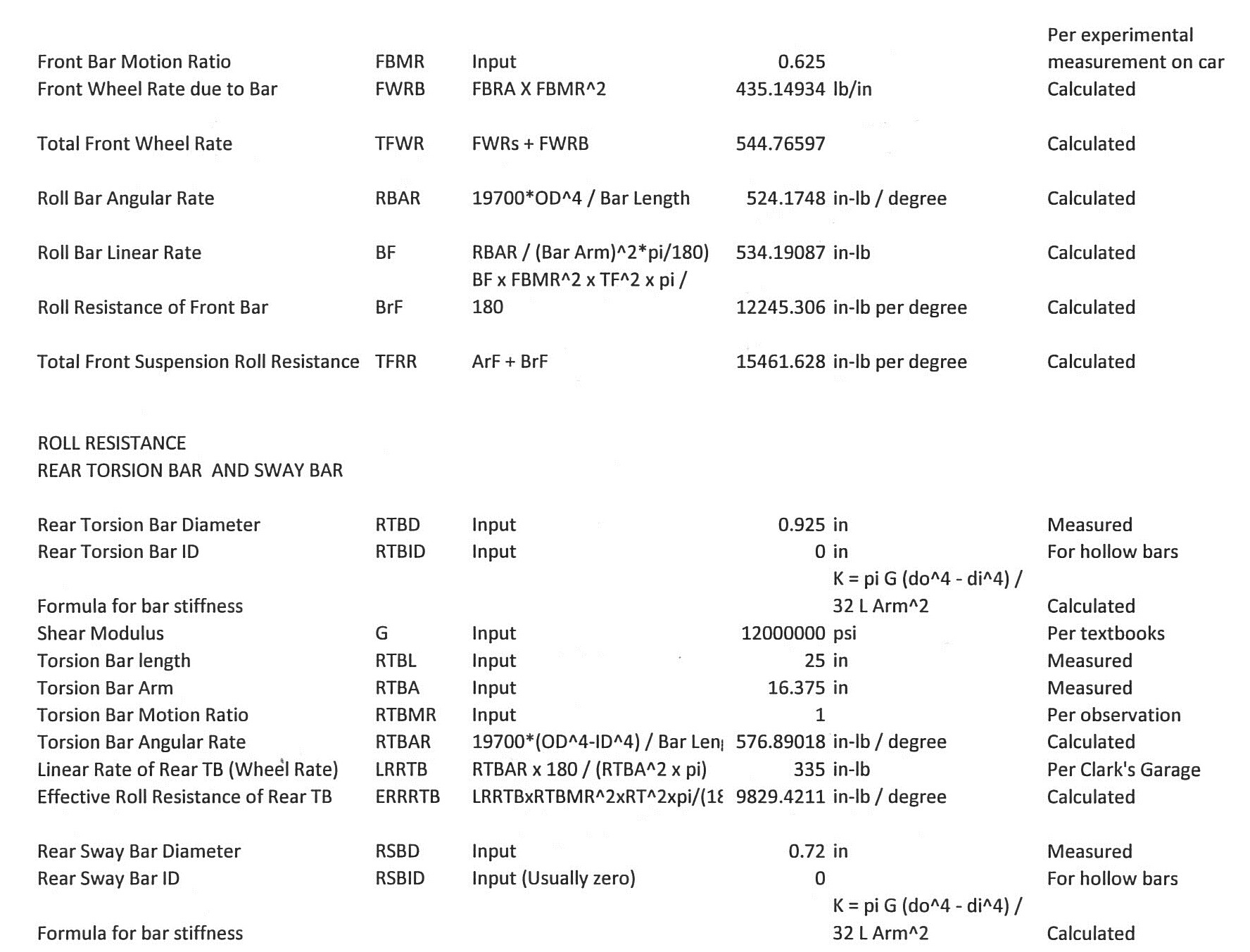
Back to the front suspension, an important parameter is the “motion ratio”. It is hard to mount the spring such that it acts directly on the tire. Due to packaging constraints, the spring force is applied inboard of the tire centerline. The term “motion ratio” is simple the distance the spring compresses as a ratio of wheel movement during compression. This can be measured directly. In the following photos, a bottle jack is placed under the wheel hub. Raise the jack until the spring is compressed, such that the car is starting to rise. Stop there. Lower the hub 1″ and see how far the spring moves. How I do this is that before I lower the car 1″, I put an electrical tie wrap around the shaft of the shock, next to the point where it comes out of the strut housing. Then I lower the hub 1″. I then measure how much space has been opened up between the tie wrap and the top of the strut housing. On my car, the distance was 5/8″. This value, divided by 1″, is the motion ratio. So in the spreadsheet you see the motion ratio for the front spring listed as 0.625. This term is important in that the spring only exerts 5/8’s of its force on the wheel. On the other hand, the motion ratio at the rear is 1.0. This is because the torsion bar setup used by Porsche applies 100% of the torsion bar resistance on the wheel. That is one advantage of a torsion bar system. The end result is that going from 175 lb/in springs to 200 lb/in springs in the front actually has a very small effect on the net front spring rate, as the net increase at the wheel is only 5/8’s of 25 lb/in.
Which leads us to sway bars. Sway bars might be better referred to as anti-rotation bars. Sway bars span between the two wheels at the front or rear of the car. They effectively transfer some of the compressive forces on the loaded side to the unloaded side. It shares the cornering load to the unloaded side, so to speak. They also reduce the total amount of body roll during cornering. Sway bars only resist roll in cornering. They do not affect the “dive” of the front end during braking.
Getting the information needed for the sway bars is basically a measurement process. If you simplify the shape of the sway bar to a “C” shape, the height of the C is the distance that the sway bar spans across the width of the car and the two “legs” of the C is the distance from the center of the sway bar back to where it attaches to the car. On this car, the bar is 31″ across and extends back 7.5″ to its mounting point. You also need to measure the diameter of the sway bar. This measurement needs to be as accurate as possible, as the diameter of the sway bar is raised to the 4th power, which makes it a very dominant term in the equation.
Sway bars also have motion ratios. The concept of the same. Raise the hub. Measure the distance from the floor up to the point where the sway bar attaches to the A arm. Lower the hub 1″. Make the same measurement again. For this car, the front sway bar motion ratio was also 5/8″.
You will note near the end of the above spreadsheet that the roll resistance of the sway bar (BrF)is 12,245 in-lb/degree. This is the opposite of spring rate but means that if the cornering force of the car causes the car to roll 1 degree that the sway bar will be applying 12,245 in-lb of resisting torque. The similar term for the front springs (ArF) is only 3216 in-lb/degree. This means that for the 944 front suspension, the sway bars are doing most of the work to resist cornering forces.
The situation is similar at the rear. You measure the diameter, width, and distance from the center of the sway bar to its attachment point. At the rear, the motion ratio of the sway bar is only 0.43. This means it is less effective.

At the rear, the torsion bar term (ERRRTB) of 9829 in-lb/deg is greater than that for the sway bar (EFFFSB) of 4121 in-lb/deg. So you get more bang for your buck from larger rear torsion bars than you do larger rear sway bars.
So we have input all the required values and can see the desired result. The numbers to look at above are the Total Outer Front Tire Load of 1064 lb and the Total Outer Rear Tire Load of 1077 lb. They are almost equal to each other, which is a very good indication that the suspension changes made do not adversely affect the neutral balance of the 944 suspension design.
Although not shown above, if I were to increase the front sway bar size by just 1/4″, the front load shift would increase to 1195 lb versus 947 lb at the rear. The car would no longer be balanced and would probably oversteer due to the reduced grip at the rear.
Unfortunately, the right suspension set-up for your car is not just a matter of spreadsheets. There are many other factors that come into play. Some can be evaluated mathematically. Some can be evaluated on expensive simulators or “shaker” rigs. Some can only be explored at the track. At a minimum, I feel that the suspension set-up that I have chosen for this car is in the right ballpark. Unfortunately, I have found that I am not brave enough, talented enough, or rich enough to consistently explore the cornering limits on my cars. But by and large the two 944’s that I have taken to the track seem to be well behaved with no obvious bad habits. So in that sense, they are great fun to use in a track environment. And that is what counts!

Discussion
Comments are closed.