CHECKING CORNER WEIGHTS ON MY 1967 E-TYPE 2+2
Introduction
After reading the book “How to Make Your Car Handle” by Fred Puhn and knowing that I had a HPDE track event coming up for the 1967 E-Type 2+2, I got motivated to check the weight distribution on the tires i.e. I wanted to check the “corner weights”. I also wanted to try and correct a problem where at the rear of the car, the left side was about 1″ lower than the right side, i.e. the car was tilted.
Fred Puhn’s book “How to Make Your Car Handle” and others, such as http://grassrootsmotorsports.com/articles/understanding-corner-weights/, do a better job of explaining this than I can. But to summarize:
Every car has a somewhat fixed weight distribution that rests on the 4 tires. Major items that affect the weight distribution are the location of the engine, the transmission, and the rear suspension. Smaller weights that can vary are that of the gasoline, the driver, and a passenger if present. Formula One cars put the fuel tank near the middle of the car so as the fuel burns off during a race, the reduced weight is evenly distributed amongst the 4 wheels. On any 2 seat car, the driver weight will be offset to one side although the presence of a passenger will tend to balance that effect out. In a right hand drive (RHD) E-Type, the driver weight on the right side is balanced somewhat by the fuel tank being placed on the left side at the rear of the car and the battery being on the left side at the front of the car. LHD cars experience the worst case scenario as the driver, battery, and fuel tank are all on the left side of the car.
To provide “balanced” handling, it would be best to have equal weights on all 4 corners of the car. In that way, each tire is loaded about the same and during cornering, the 2 tires on the outside of the turn receive additional load equally. Mid-engine cars are a design that allows the weight distribution to work out pretty well. Another advantage of balanced weight distribution is more consistent braking performance.
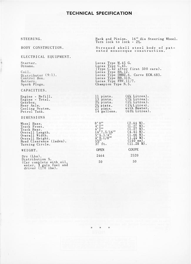
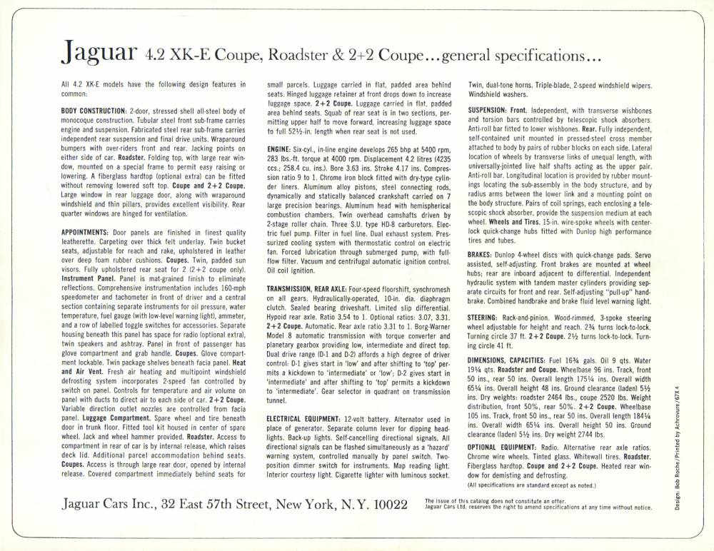
One parameter that is used to reflect how well (or poorly) a cars weight distribution works out is the ratio of the weight on the front axle to the rear axle. Expressed in percentages, a perfect split is stated as “50/50”. A front engine / front wheel drive car may be 60/40. Looking at the original specifications for a 1961 E-Type coupe (http://www.jag-lovers.org/brochures/xke/egt_tech_17_l.jpg), Jaguar quoted a 50/50 front to rear ratio. They also quoted the car weight as 2520 pounds with oil, water, a 170 pound driver, and 3 gallons of fuel. The dry weight of my car, a 2+2, is quoted as 2744 pounds (http://www.jag-lovers.org/brochures/xke/xke-2_2_harbour6page_6_l.jpg). As there is no discussion in the brochure otherwise, I am assuming that the weight distribution on the 2+2 is also 50/50.
So for perfect weight distribution in my car, you might expect that you would shoot for 2744 / 4 = 686 pounds on each corner. Driver, fuel, and/or passenger would add weight to this value.
When you mount the car on springs at the 4 corners, the actual weight at each spring can vary depending on the position of the spring. To use a crazy example, if you have three 12″ long springs and one 10″ long spring, as you lower the car on the springs the car will rest on the three 12″ long springs and the 10″ long spring will not even contact the ground. Then you will have a 3 legged car that will handle very strangely! So by checking corner weights you are really checking to see if the 2 front springs and the 4 rear springs (on an E-Type there are dual springs at each rear corner) are engaging equally. If they aren’t, you can adjust them up or down using shims (at the rear) or by re-setting the torsion bars (at the front) until the weights are at least close to the target values. Doing so should result in the best handling and braking characteristics for the car.
")
")
The Process
The first thing I wanted to find out was the static weight distribution on my car in a “track” configuration, which would be a single driver, spare tire removed, and about ½ tank of fuel. To get a static value (versus the values with springs acting) I lifted the car and added blocks of wood at the four corners to cause the springs to be in-active.
Following is a summary of my work. Detailed actions and results are contained in the Appendix (below)
I’m going to report my weight results in the format:
LF RF
LR RR
Total
All weights are in pounds.
Here are the Static Weight Results with 7 gallons of fuel and 190# (of sand) to mimic a driver.
796 647
798 706
2947
As you would expect, the car is heavier on the LH side. You can also see that the front to rear weight distribution on the LH side is almost exactly 50/50.
After adjusting the LF torsion bar and all 4 rear spring positions, here are the Final Results.
765 704
826 649
2943
Conclusion
If I was building a race car, I would probably want to continue to fine tune the settings of the springs and the torsion bars to bring the weights a little closer to an optimum value. In particular, that heavy weight in the RR corner due to the gas tank is a problem for a racer. But at this point, to get a more balanced weight would probably require some surgery, like moving the gas tank to the opposite side of the car. I don’t think my usage of the car as a touring car that will occasionally visit the track warrants such actions. Of course, adding a passenger will move weight to the RH side of the car and will provide pleasant companionship to boot. So maybe the best conclusion is always take a friend with you when you go for a ride in your E-Type!
Appendix
First some notation. The obvious: LF = left front RF = right front LR= left rear RR = right rear TW = total weight
I’m going to report my weight results in the format:
LF RF
LR RR
TW
Case 1: This was the as-found car with very little gas in the tank (maybe 2 gallons) and no occupants. Spare tire installed.
728 663
691 672
2755
This didn’t look bad. Left side of the car a little heavier than the right side. Front to rear about 50/50. Note that the 2+2 is reported in the literature to be about a 50/50 weight distribution front to rear.
Case 2: I “jounced” the suspension, i.e. I pushed down firmly at all 4 corners and let it spring back. I just wanted to see what this would do to the numbers. As you can see, every number changed a little bit but not too much.
720 673
701 664
2758
Case 3: I really wanted to get the rear of the car level. Now that I can see it is tilted, it bothers me. Fortunately, I have some nice shocks that I purchased from Classic Jaguar in Austin TX years ago that have adjustable “spring perches” via the outside of the shock body being threaded. This makes adjustment at the rear much quicker. For starters, I went a small amount. Noting that there are 2 shocks per side, I raised the perch on the LH (low) side shocks by ¼” and lowered the perch on the RH (high) side shocks by ¼”. I didn’t expect much and found the tilt went from 1″ total to ¾” total, side to side. Here are the corner weights.
688 704
729 632
2754
As you can see, the RF and LR weights went up. I had “jacked” the car. Not so good!
I went away and thought about this for a few days. I decided I wanted to get a better baseline of weight values to work against. What I decided to do was to lift the car up and insert rigid links at the spring and torsion bar locations. I wanted a “rigid” suspension. This turned out to be pretty easy. I jacked up the rear at the center and put in stout wood pieces from the hub carrier up to the fixed IRS cage. When I lowered the car off the jack, the blocks took all the load and left the springs in-active, so to speak. I did the same at the front. I jacked up the car at the center and put in stout wood pieces to take up the reaction from the torsion bar and transmit the weight directly from the frame to the lower A-arm.
Now I proceeded to get a set of “ideal” or static weights.
Case 4: Minimal gas, no driver, with spare.
749 644
668 688
2748
Case 5: Same as Case 4 but spare removed from the car. The spare weighs 34#.
751 649
654 660
2714
Case 6: Same as Case 5 but I added a 5 gallon container of water on top of the fuel tank, which is probably the equivalent of 6 gallons of gasoline and effectively mimicked ½ tank of fuel.
753 637
694 674
2758
Case 7: Same as Case 6 but added 190# (of sand) to mimic a driver.
796 647
798 706
2947
I would believe Case 7 to be pretty representative of the car in “competitive” trim for a track event or autocross. Note that front to rear weight distribution on the LH side was almost exactly 50/50. On the RH side 48/52. LH side of the car definitely heavier, as is to be expected with a LH drive car. So I thought this to be a pretty good set of target values.
Case 8: I took out the wood blocks in the front and set the front on the torsion bars. The rear was still blocked rigid.
724 723
872 630
2950
Case 9: I took the wood blocks out of the rear so all 4 corners were on springs.
735 711
860 640
2947
There was that “jacking” effect again, with the LR being too heavy to a scary degree. I decided to tackle the front end, as my ride height on the LF side has always been a little lower then the RH side. Not much, on the order of a ¼”.
Case 10: I had purchased some heavy turnbuckles from McMaster-Carr for the next step. I took out both front shocks. I installed the turnbuckle in place of the LF shock. I elongated the turnbuckle until the corner weights looked better. In effect, I was raising the LF ride height and added weight at that corner.
798 649
797 703
2947
Bingo! Looking back at my baseline “rigid” case, the numbers were almost exactly the same! This was looking promising. My before and after measurements indicated that I had extended the turnbuckle by only ¼” to achieve this very good weight distribution. Also, front ride height was equal to within 1/8″.
Case 11: As many of you will appreciate, going from the turnbuckle to the adjusted torsion bar is no easy feat. What I did was to disconnect the various parts and pieces to free up the torsion bar and the lower A-arm to a neutral position i.e. the torsion bar was unloaded. I put the turnbuckle back in and carefully set its length to match the existing space. Then I took the turnbuckle out and carefully made it ¼” longer. Then I released the torsion bar completely at the reaction plate and put the turnbuckle back in, holding the A-arm at the new position ¼” lower (at the shock). Finally, I went through that damn trial and error process with the vernier effect of the different spline counts at both ends of the bar to find the perfect position for the rear mount. With the 2 bolt holes into the reaction plate lined up, I re-assembled the torsion bar in its new position. I re-assembled the upper A-arm and put the wheel back down on the scales. Here are the numbers I got.
783 661
800 691
2935
I had strayed from my “perfect” numbers but things were still pretty close.
Case 12: Puhn and others caution you to not let your sway bars work against you. After hooking up the sway bars here are the numbers.
758 699
828 650
2936
As you can see there is a “jacking” effect. If I had adjustable links on my sway bars, I could have made all of the effect go away but I don’t (have adjustable links) so I decided to stick with what I had!
Case 13: Same as above but after hooking up the front shocks.
765 704
826 649
2943
As you can see, even hooking up the shocks has an effect!
Just for kicks, since HPDE’s occur with a passenger/instructor. I sat in the passenger seat and collected one additional set of numbers. It looks like I weigh 195#.
770 754
863 747
3137
I have learned never to check ride height until taking a long shake down run. After taking my standard Sunday morning loop drive, I found the front end ride height to be a little on the high side but within 1/8″ of being level. More amazingly, the rear end was now almost exactly level! Some times you get lucky :
Alignment: I do all of my own alignment checks. I checked toe-in and found it to be way off. I re-set for just the slightest amount of toe-in. Then I checked camber. I do not have any shims at the upper A-arm mounting brackets, which should result in the maximum available amount of negative camber.
LH -0.6 degrees
RH -0.1 degrees
Factory spec is positive ¼ degrees +/- ½ degree. For track work more negative is better. Since I can’t make it any more negative, I will leave it as is.
So that is my experience with corner weights. Very instructive. We’ll see if I can spot any differences or improvements at the track!

Discussion
No comments yet.