Recently, I had an independent inspection performed on my 2007 Porsche Cayman S as required to attend a track event. One item the mechanic brought to my attention was that grease was being expelled from the edge of the rubber boot on the outer constant velocity (CV) joint of my rear drive shafts. There was a significant buildup on the inside of the wheels so it apparantly had been going on for a while.

The shiney spot is where I scraped off a little bit of the grease buildup.
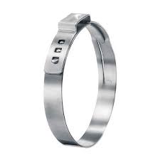
A little sleuthing on the internet determined that this is a common problem. Apparently, the Oetiker clamps loosen up a small bit and allow some of the grease that the CV joints are packed with to get out. I decided to order new boots for the inner and outer CV joints and new “Oetiker” clamps. Oetiker- a funny word. Here is what Wikipedia says: A stepless type of ear clamp was invented by Hans Oetiker in Horgen, Switzerland, which eliminates steps or gaps on the inner circumference of the clamp. This is said to provide uniform compression and a 360° seal. Such stepless clamps are claimed to be well suited to applications involving thin-walled hoses, supposedly with higher retained loads. This suggests they should be considered for difficult to seal applications such as molded plastics or other less malleable materials, commonly used in the automotive industry. They require a special tool to properly install them so I bought one of those too. BTW, I purchased my boots, clamps, and tools from 5150motorsport.com. They were great to work with.
Getting started, I consulted my Porsche shop manual. The instructions were pretty basic.
1. Remove the center caps from the wheels. Using a large breaker bar and a 32mm socket, release the approximately 340 ft-lbs of torque on the axle nut. This may require an assistant to apply the brakes.
2. Put the car on a lift and remove the wheels.
3. Remove the transaxle support plate and the diagonal braces.
4. Fit a protective cover on the axle shafts (Note- I did not do this. Maybe a bad decision!)
5. Remove the M10 internal hex bolts at the transaxle CV joint.
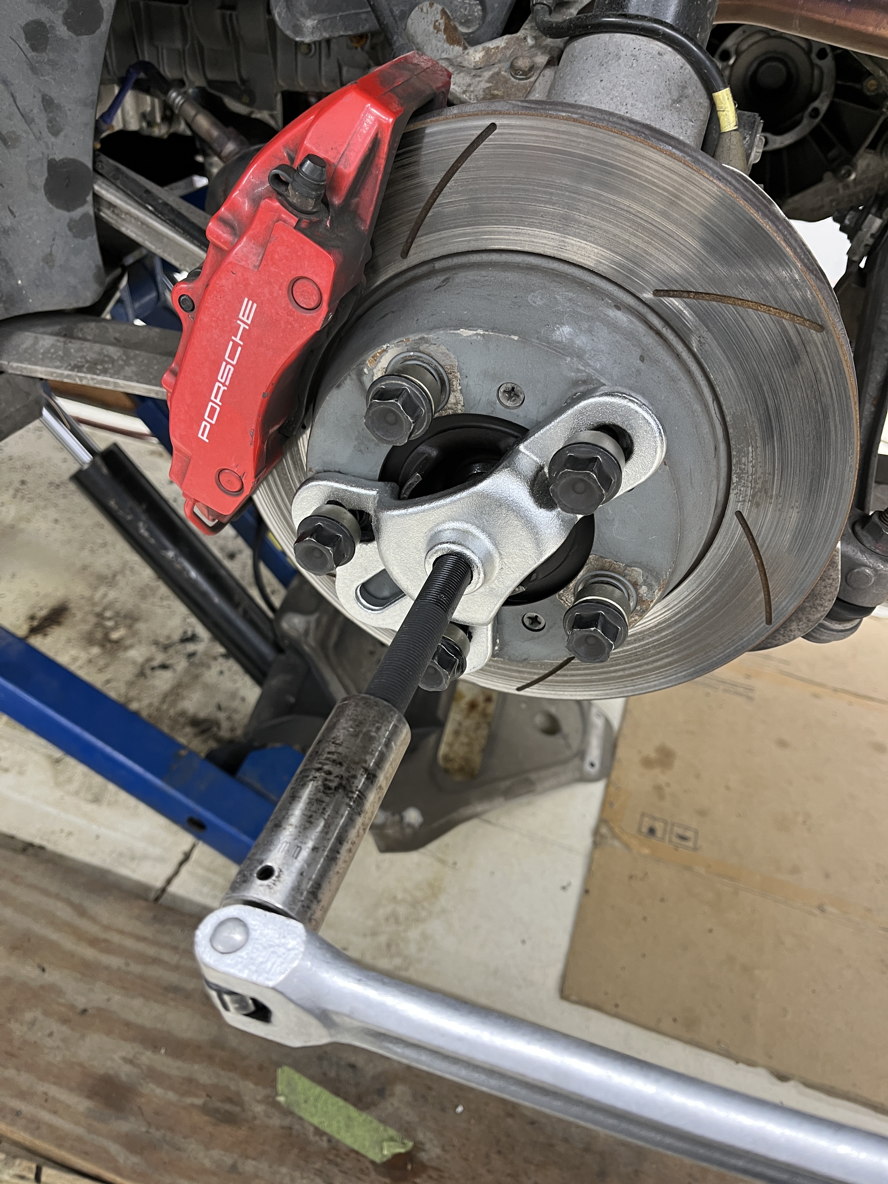
6. Use universal drive shaft/wheel hub extractor carefully press out the drive shaft until the shaft can be moved by hand. Remove drive shaft.
Removal of the M10 internal hex bolts at the transaxle CV joint was straightforward, although I always pucker a little when having to release highly torqued internal hex bolts. Drop that end of the drive shaft so that it dangles below the transaxle. I tried tapping on the end of the splined shaft (with the nut installed) with a hammer but it was pretty firmly stuck. I had a set of puller tools and was fortunate to find one that I could use to drive the splined drive shaft inward and thus release it from the hub. The tool I had did the trick and the splined driveshaft moved inward and released itself.
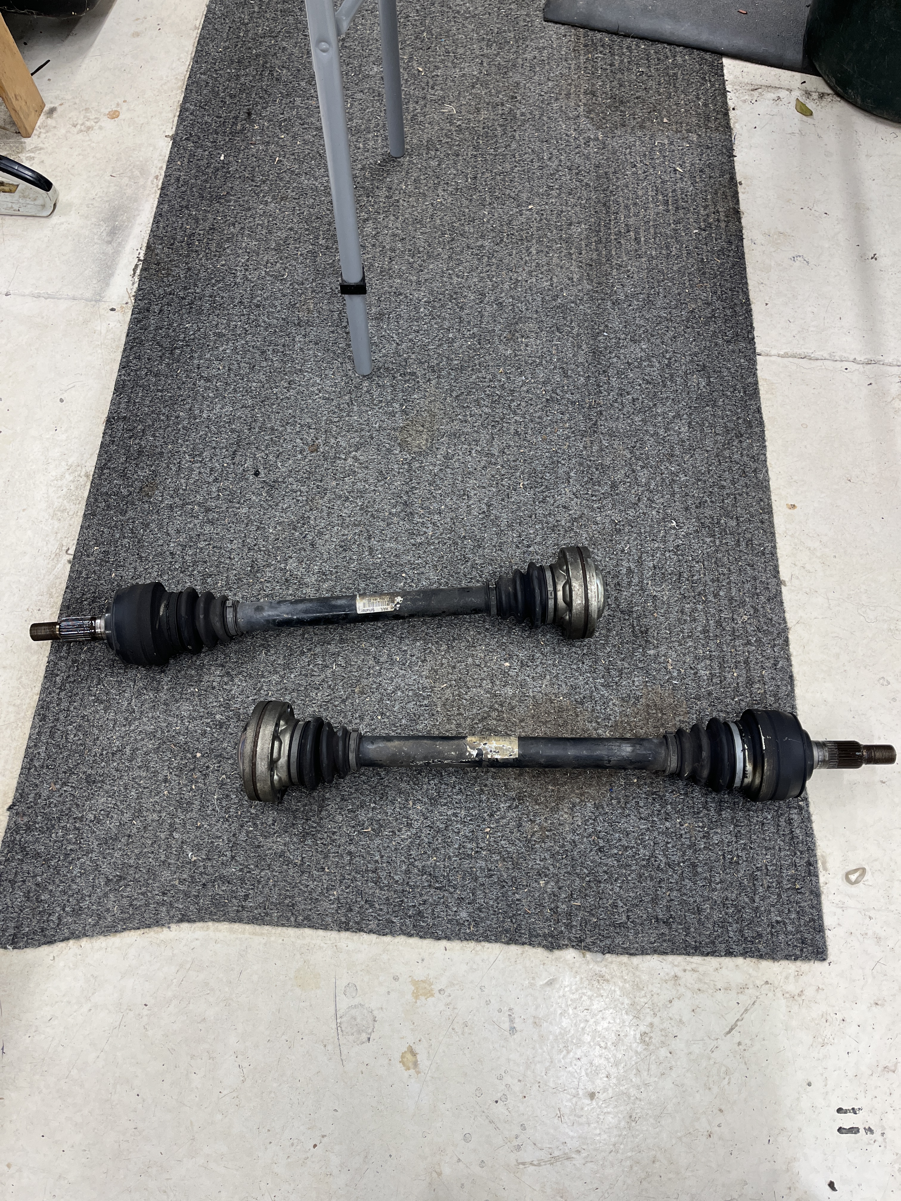
I didn’t realize it initially but one drive shaft is longer than the other. Upon reinstallation, it would be impossible to install them in the wrong positions but it is something to keep in mind.
The boots are not split so to get them off and on, one of the CV joints needs to be removed from the driveshaft. I decided to tackle the one at the transaxle end. There are metal covers on both sides of the CV joint. One goes over the outer end of the CV joint. It is just tightly fitted over the OD of the CV joint and I was able to drive it off with a drift punch, making multiple strikes around its perimeter until it finally came off. This gave me access to a circlip on the inside, which I removed. At this point you need to drive the splined end of the drive shaft out from the ID of the CV joint. You need to support the inner race of the CV joint when doing this. In retrospect, you probably should drive the metal cover off the other side of the CV joint first, to avoid damage to it. I didn’t do this. Since I was going to replace the boots, I cut the clamps off with a wafer disc and carved the boots apart with a knife. Then I was able to get the CV joint off the splined drive shaft. So far so good.
I put my attention to the other end. I again cut the Oetiker clamps off with a wafer disc and cut the boot off with a knife. Sometime shortly after this, I noticed that the sheet metal cover that the boot attached to was not round. Damn. In retrospect, I don’t remember banging it on anything during removal but it could have happened. That is probably why the shop manual calls for a temporary protective cover. It is also possible that the damage was pre-existing and explains why the boot was leaking. Regardless, it needed to be fixed. I thought I would take the cover off and put it on a round mandrel and beat it into shape. But I found the cover is pinched over a groove on the CV joint. I would have to destroy it to get it off. Double damn!

It was at this point that I decided to see about purchasing new CV joints. I’m not going to say they are unobtainable but they certainly weren’t a commonly listed item on the websites of Porsche parts suppliers. The Porsche PET does list individual part numbers for the transaxle side CV joint, as well as the sheet metal caps, and the rubber bellows. Disturbingly, to get the roadside CV joint, Porsche only lists it as a complete drive shaft assembly.
I frankly did not know the condition of my CV joints. They did have 100K miles on them and I suspected if I took them apart and cleaned them up, I would likely see some evidence of wear. So my brain started to shift towards purchasing complete new assemblies. Just for fun, I contacted my local Porsche parts counter. We have an understanding that I get to play my “I see them at GetPorscheSilverSpringParts” card for their discounted price, which my local dealer will generally match. That got the price into the $2400 range for a pair, with tax. Then came surprising news. For one side, there were only 3 showing in the world. For the other side, there were none and the part number was discontinued. Wow! BTW, the latest part numbers for my 2007 Cayman S are 987 332 024 66 and 987 332 024 68. I reached out to GetPorscheSilverSpring and they replied that neither part was available. I then contacted Mike at 5150Motorsport to see what he could come up with. He got back to me with the somewhat surprising news that RockAuto was showing availability for new GKN drive shafts. GKN is reportably the OEM for the Porsche axles. I was able to get the pair, with tax and shipping, for $898. The RockAuto drive shafts arrived a few days later. They came in a GKN box. There was no core charge and I believe they are new items.
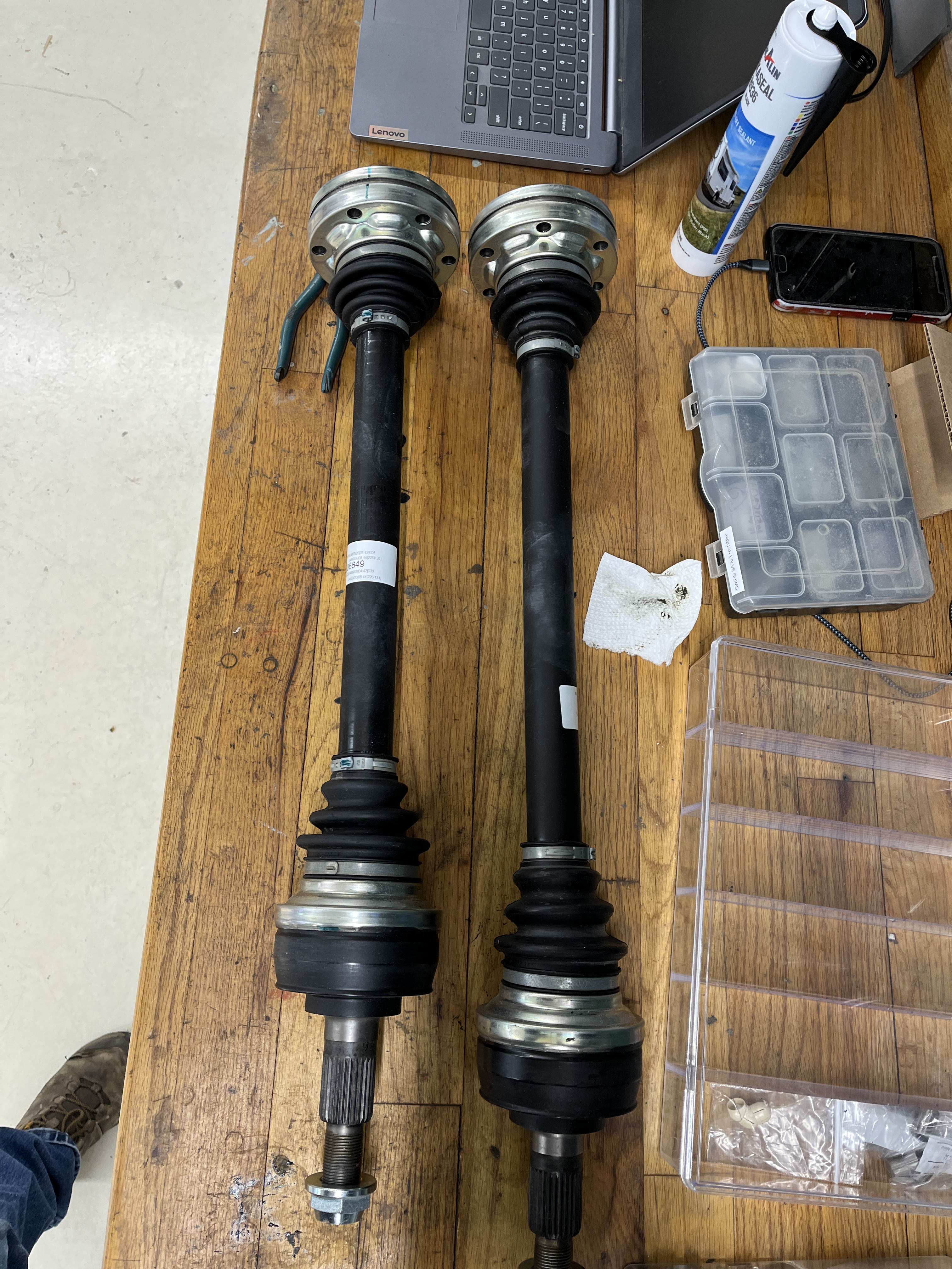
There are two different part numbers because the drive shafts have different lengths. Below are photos of a simple tape measure measurement made sticking the tape through the hub opening and stabbing it into the mounting point on the transaxle. The difference in length is clearly visible.
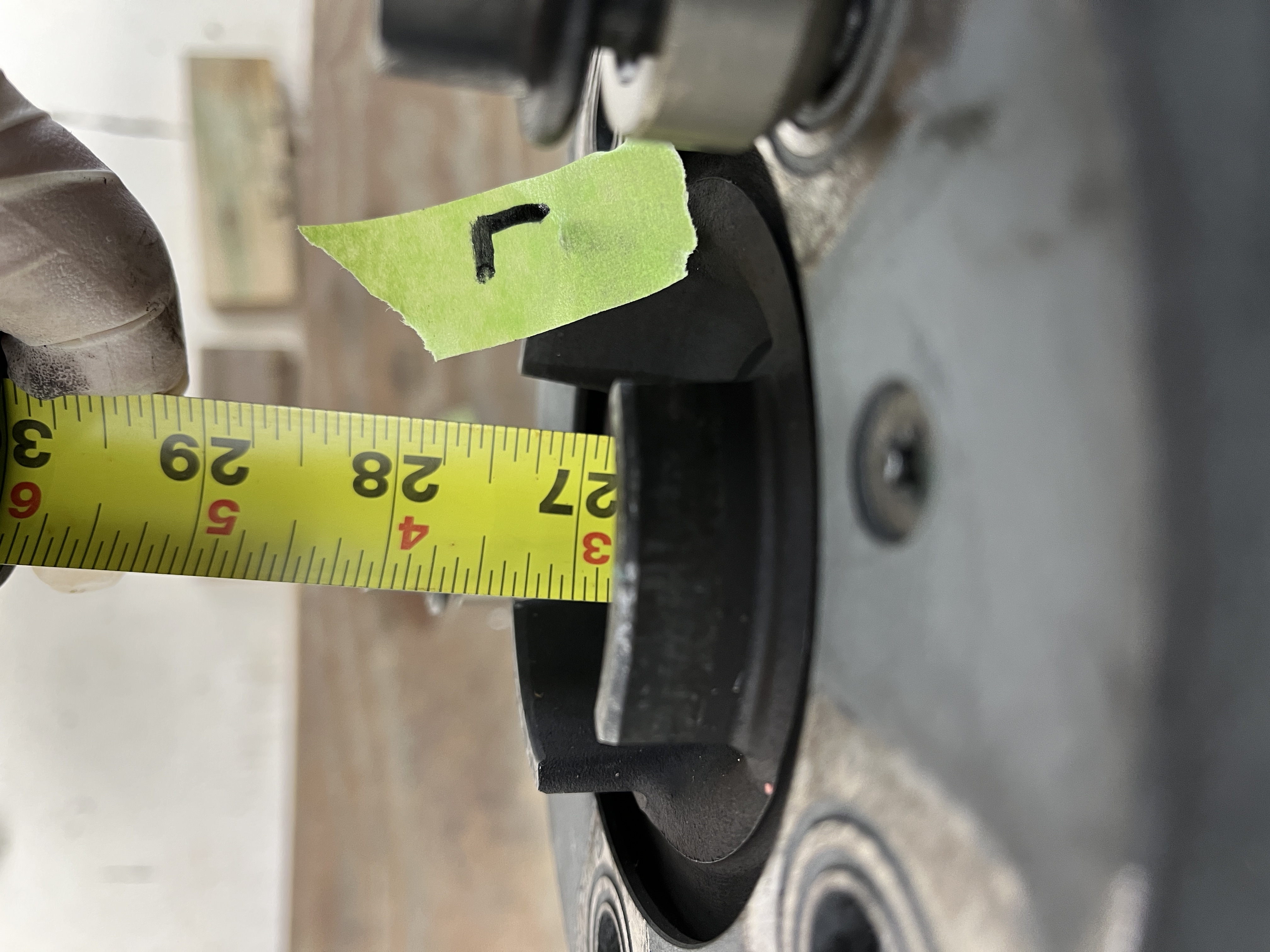

Trust me, you want to get the correct one on the correct side. Fitment is very tight, even without trying to put in a part that is 2″ too long! So this time, I came up with a temporary protective cover, which was basically just bubble wrap.

I cleaned the female splines on the hub and the male splines on the drive shaft. I added a little bit of anti-seize to the male splines. As an experiment, I tried inserting the drive shaft the “wrong way” from the outside, just to see how much the splines were going to fight me. Generally, they started to jam up after about an inch of insertion. I tried multiple clock positions and did find that certain orientations went in a little further but they are certainly tight. I then took the drive shaft to the proper location on the inside of the hub and started the insertion of the male splined end. The CV joint is stiff and the shaft wants to cock and not insert cleanly. BTW, the other end is left dangling down below the transaxle at this point. Once you get it started, you mainly have to use brute force to get it partially inserted, being mindful that there is a delicate sheet metal item under the spot where you are inclined to grab and push. Fortunately, you don’t have to get it all the way in. If you can get just a few threads sticking out on the other side, you can use the axle nut to pull it the rest of the way through. BTW, throw away the axle nut that comes with the GKN item. If you look at it, it has “upset threads”. Using this will totally skew your torque readings when making the final tightening of the joint.
Once you get the outboard end installed, you turn you attention to the inner end. The clearance while raising the dangling end of the axle with its CV joint into position is quite tight. Again, the CV joints are quite stiff, but you need to compress them a bit, using brute force, to get them into position. Once they are in position, they actually stand off a bit from their final position. Making the first bolt requires more brute force. Once you get one bolt started, you can snug it down which will pull the CV joint into a good position for making up the remaining 5 bolts. Don’t forget the washer plates.
Once I had the bolts installed, I removed them one at a time and added some blue Loctite. I then snugged them all up and torqued them to the workshop manual value, which is 60 ft-lbs. Yes, I am a foot-pounds guy. Where this pounds-feet thing got started is beyond me!
I then reinstalled the diagonal bracing and the associated plate under the transaxle. These bolts get torqued to 48 ft-lbs. As I write this I have not torqued the wheel nuts to 340 ft-lbs. Nothing nefarious here, I actually have a 3/4″ drive torque wrench that will do the job. I just need to line up someone to stand on the brake pedal while I do this. You can substitute a 1/2″ drive breaker bar, a piece of pipe, and a bathroom scale if neccesary. For instance, look for a 113 pound weight increase as you are standing on the scale, holding the pipe 3 feet from the nut and lifting upwards. I did take the time to clean up my wheels to get rid of all the grease. Mothers Aluminum wheel cleaner did the job, no issues.
So I have that job behind me. I think that is one less thing to go wrong when I do aggresive track driving.


Discussion
Comments are closed.