After my First Start and First Drive, I noticed that the warning light on the dash indicating a charging circuit fault was illuminated. This kicked off a longish repair cycle where I was able to deal with various issues and get the generator and voltage regulator systems in good running order. Following is one of my deep dives into this subject.
There is a lot of ground to cover here. Although the generator and voltage regulator system is simple by modern standards, I still had a learning curve to obtaining enough knowledge to fix my problems. My search for knowledge started with this thread on Jag-Lovers.
In particular, thanks to Mike Eck, Tom Draude, and David Langley for their help. If you really want to take a deep dive, I would recommend the following link, which will take you to a full course of study on the subject. This document is 275 pages long and I certainly didn’t read all of it. But the sections that I did read gave an excellent, relatively easy to understand discussion as to how these systems work. It is worth looking into.
In a more direct approach, there is the document “Lucas Generator and Control Box Tests” found at the following link:
chrome-extension://efaidnbmnnnibpcajpcglclefindmkaj/https://www.mg-cars.org.uk/imgytr/pdf/lucas.pdf
This document gives step by step guidance to use in troubleshooting both your generator and your voltage regulator. My generator seemed to be working, in that I could register voltage output that made rough sense. The voltage regulator (VR) on the other hand seemed to be totally dead. Because I went through a lot of deadends, I’m going to skip to the repair process that did work.
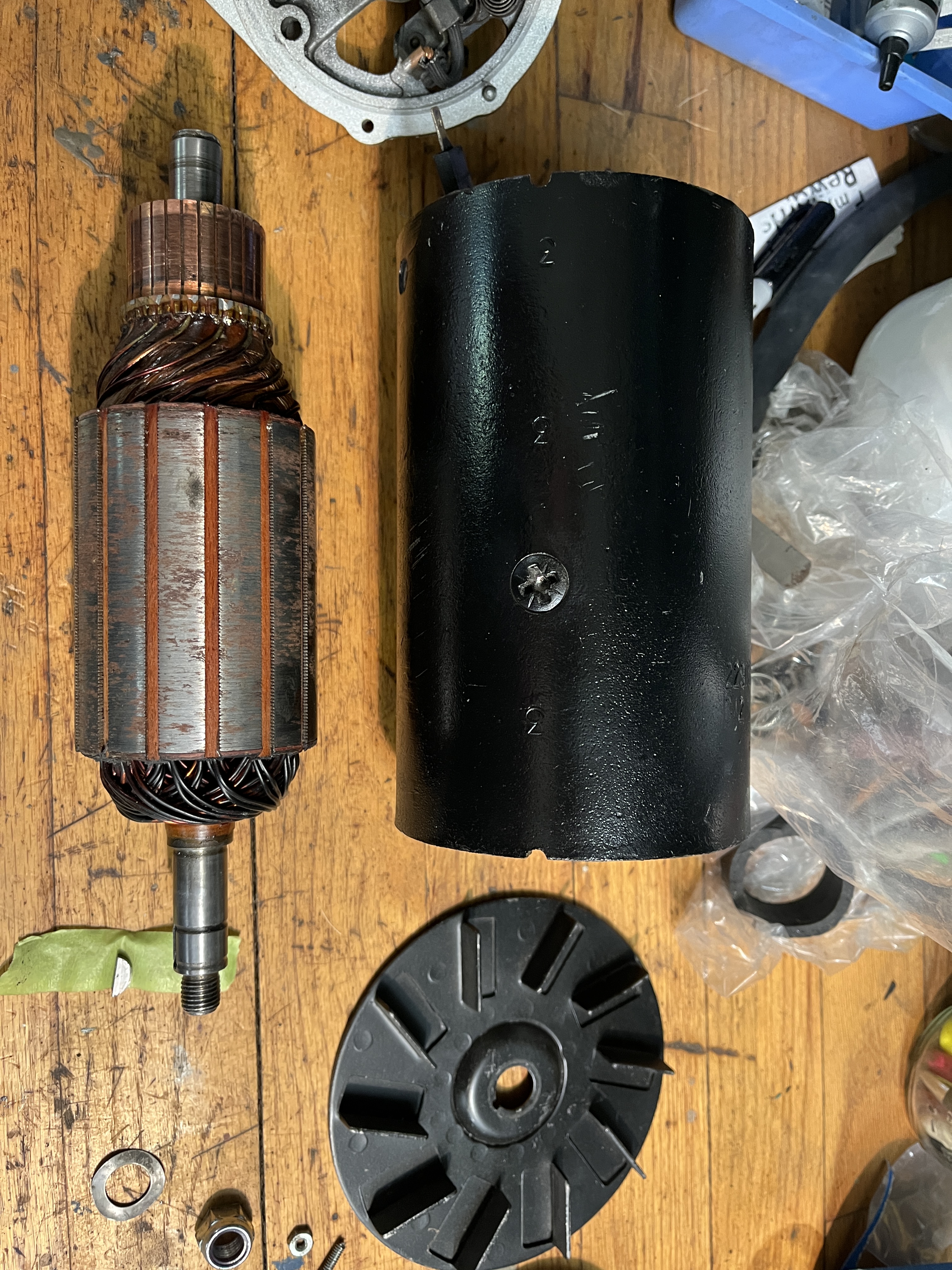
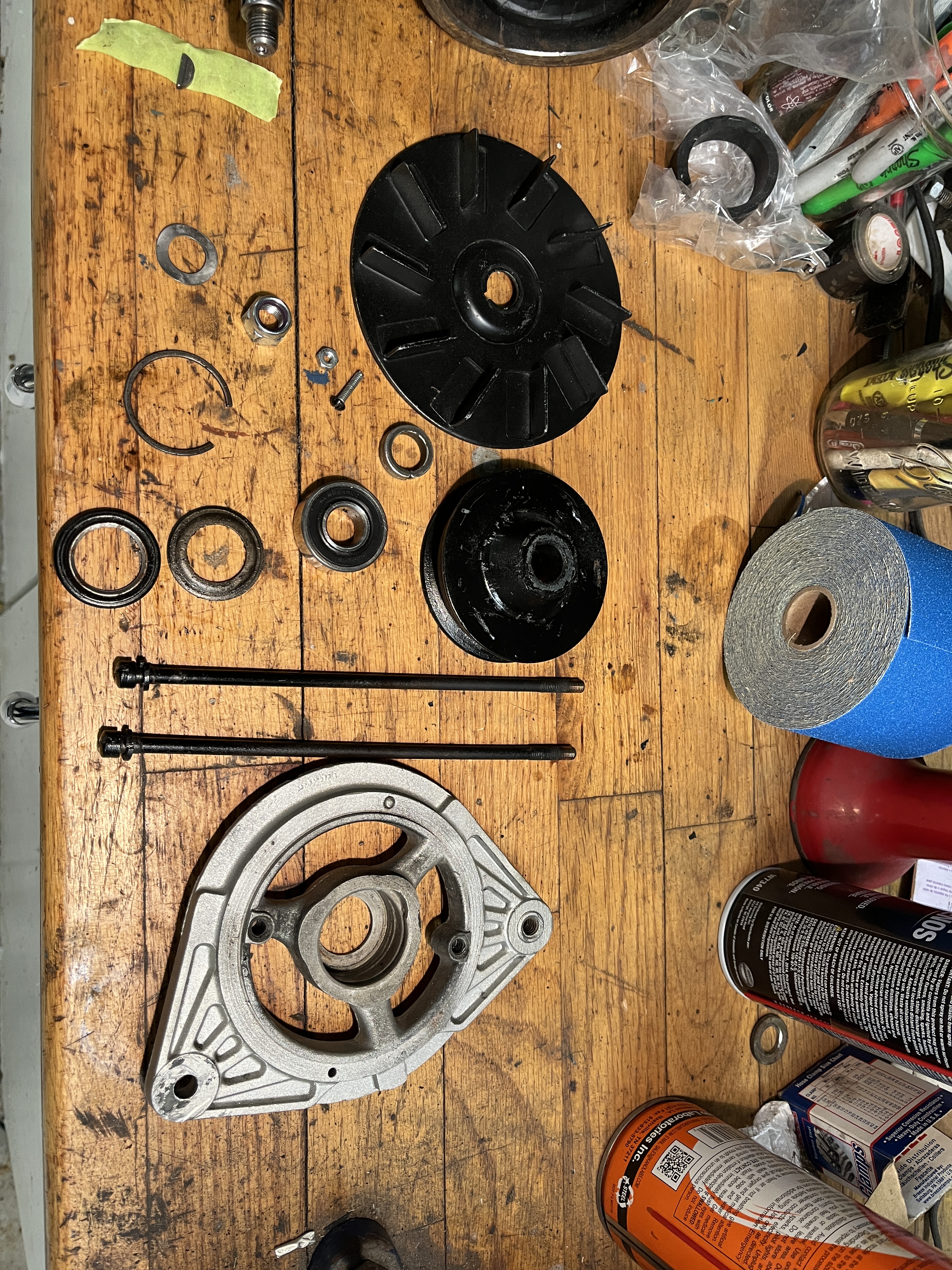
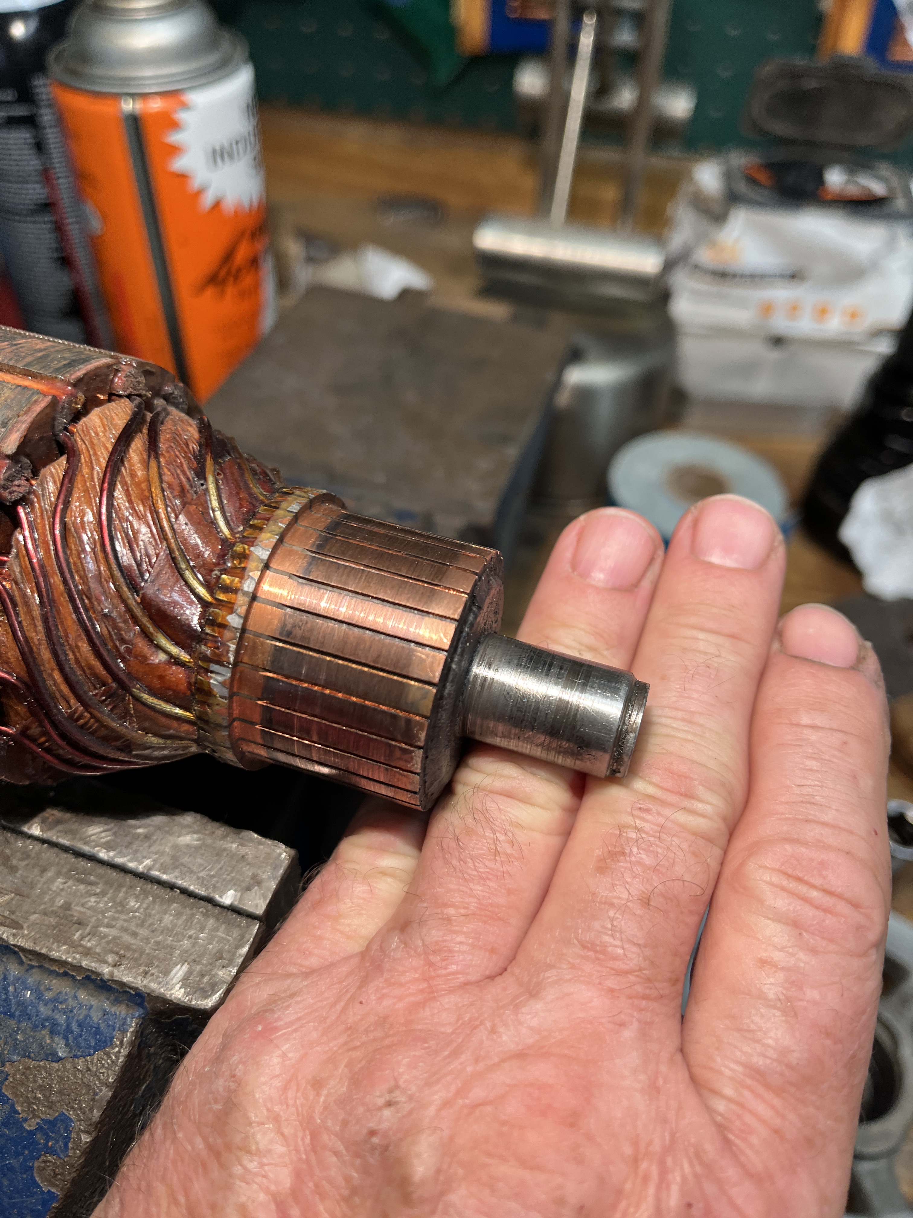
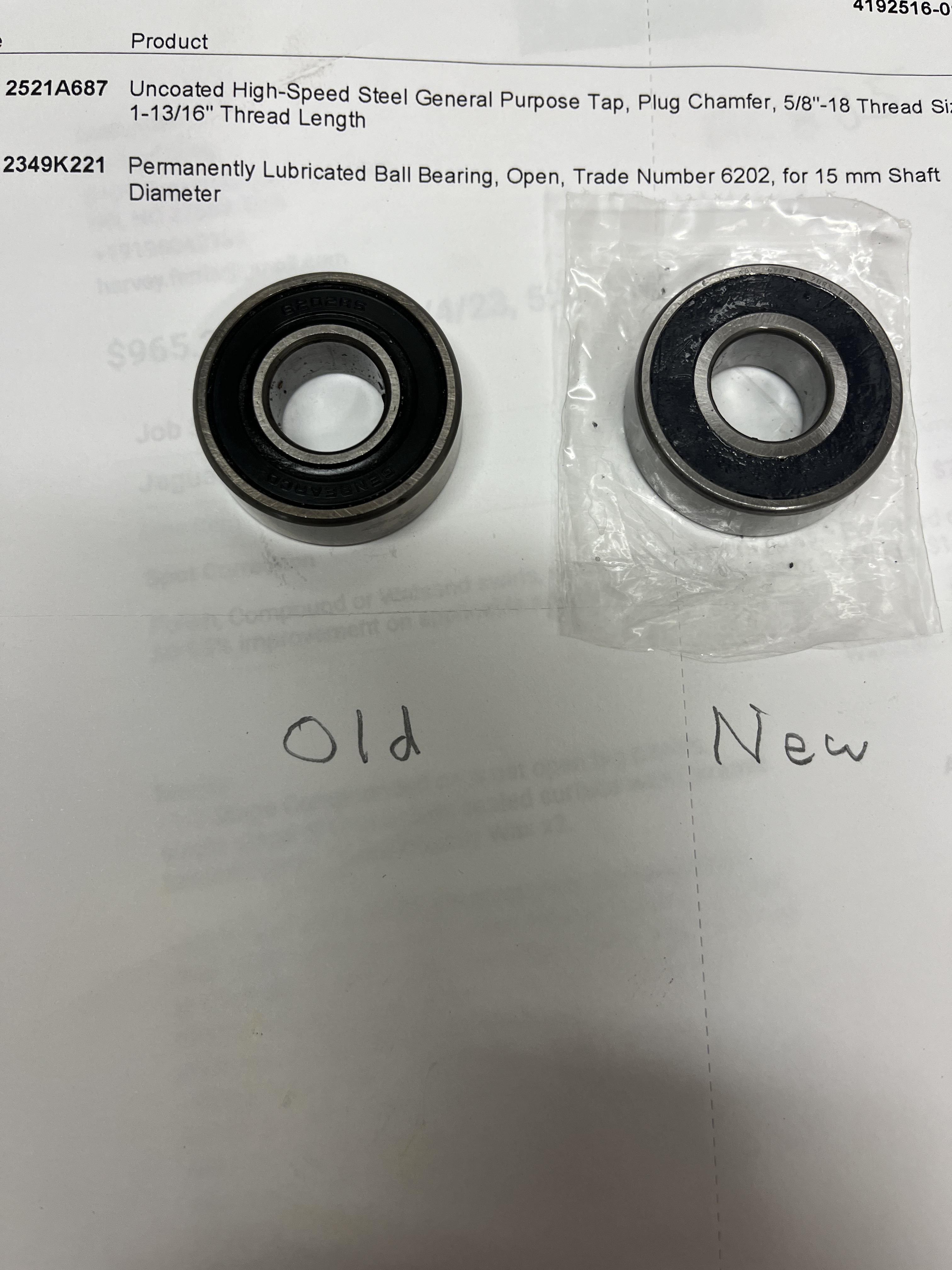
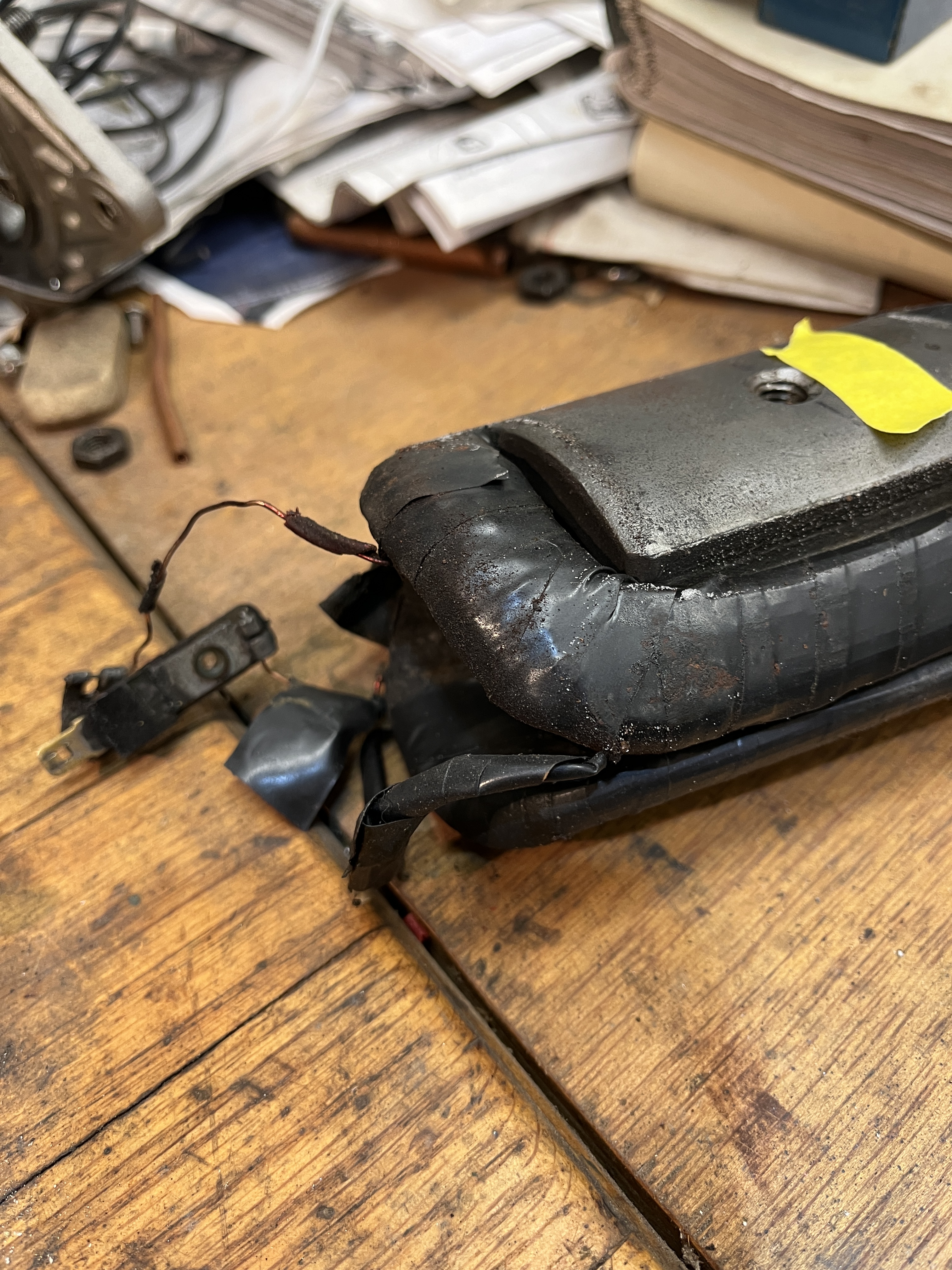
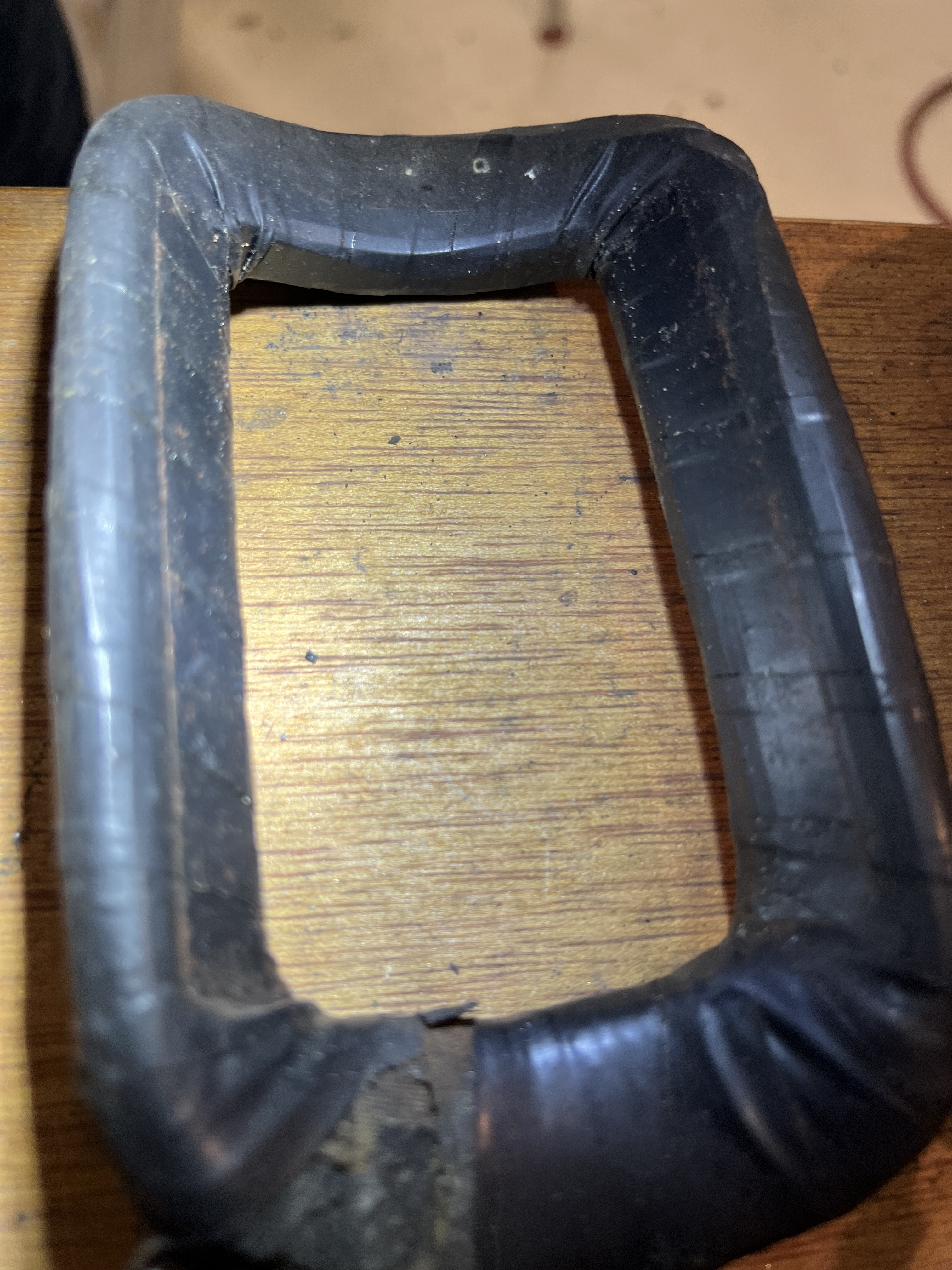
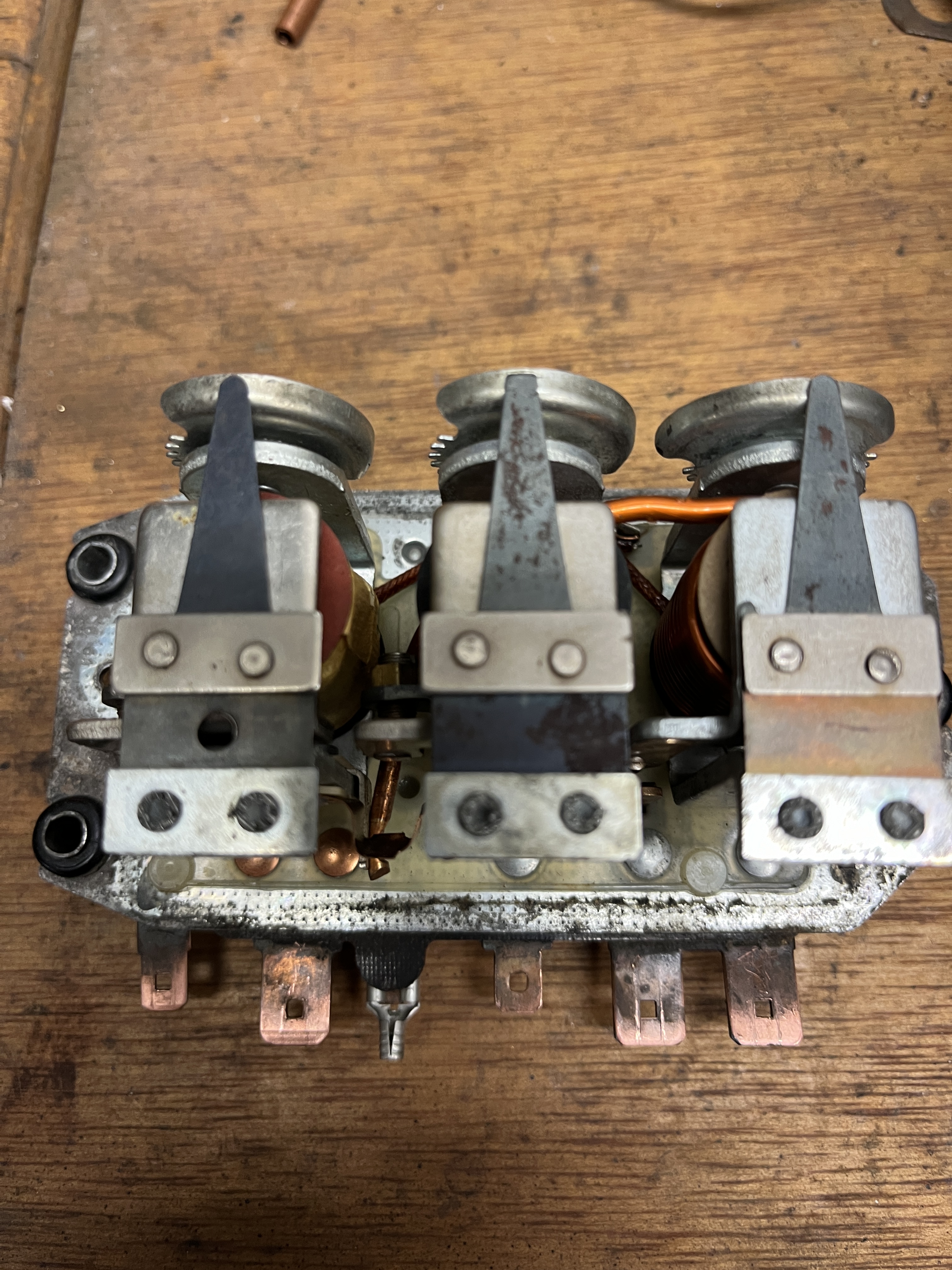
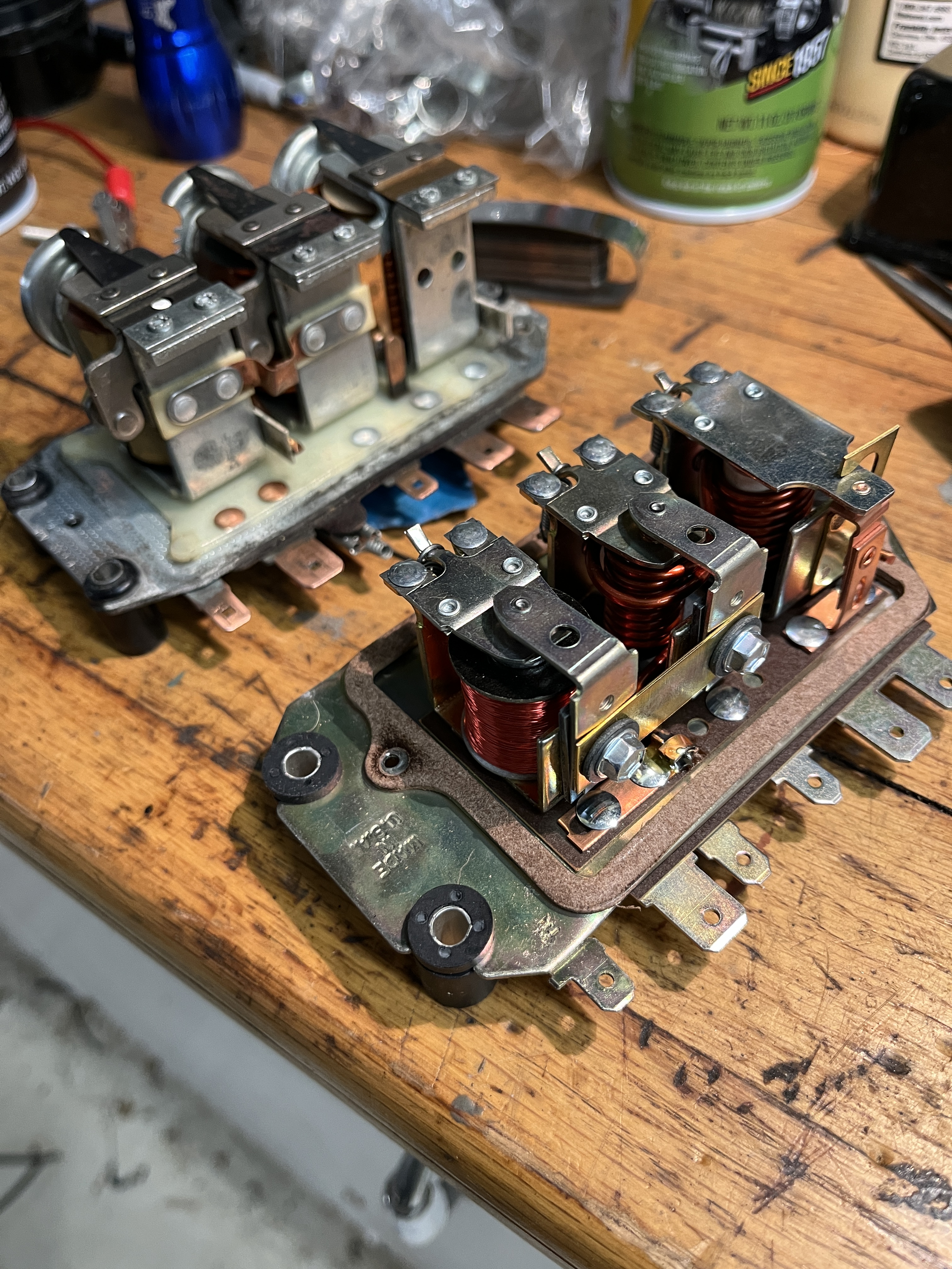
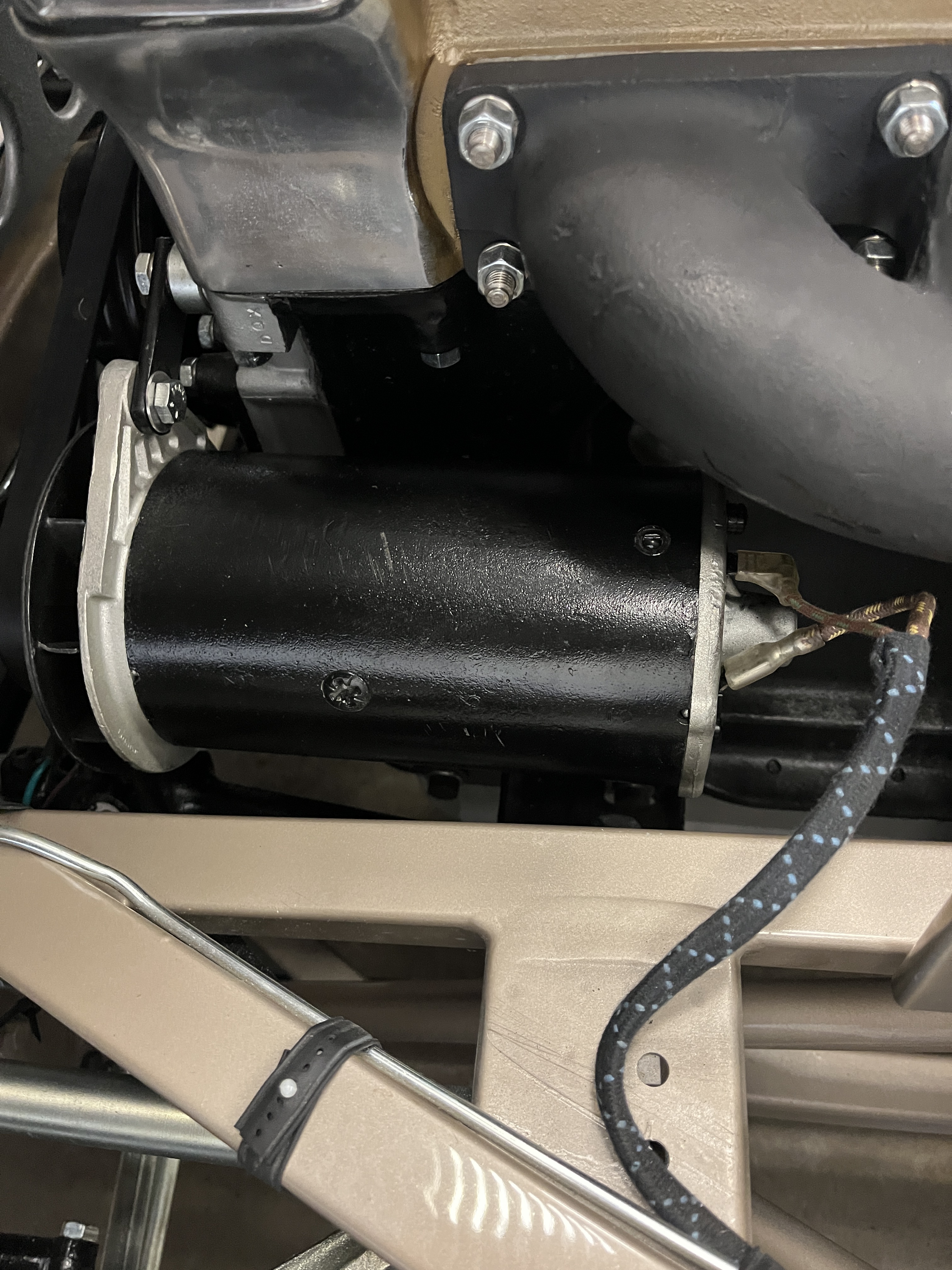
The generator “field” resistance was showing too low of a resistance. I was getting about 1.5 ohms and I should have been getting about 5 ohms. In the pictures below, I have disassembled the generator. It turned out that the “field winding” was shorted locally to the heavy curved rectangular metal piece that the field wires were wrapped around. There are two of these and internally, they become electro-magnets. I “re-taped” the loop of wires that was shorted and this worked. While I was in there, I decided to replace the bearings at both ends of the armature shaft. One is a standard ball bearing, currently available from McMaster. The other bearing is an “oilite bushing”. I obtained a new old stock bushing from a source on Ebay. I am pretty sure the bad bearings were allowing the armature to scrape the field wiring and caused the local short. I did not replace the brushes as they looked to be in good condition.
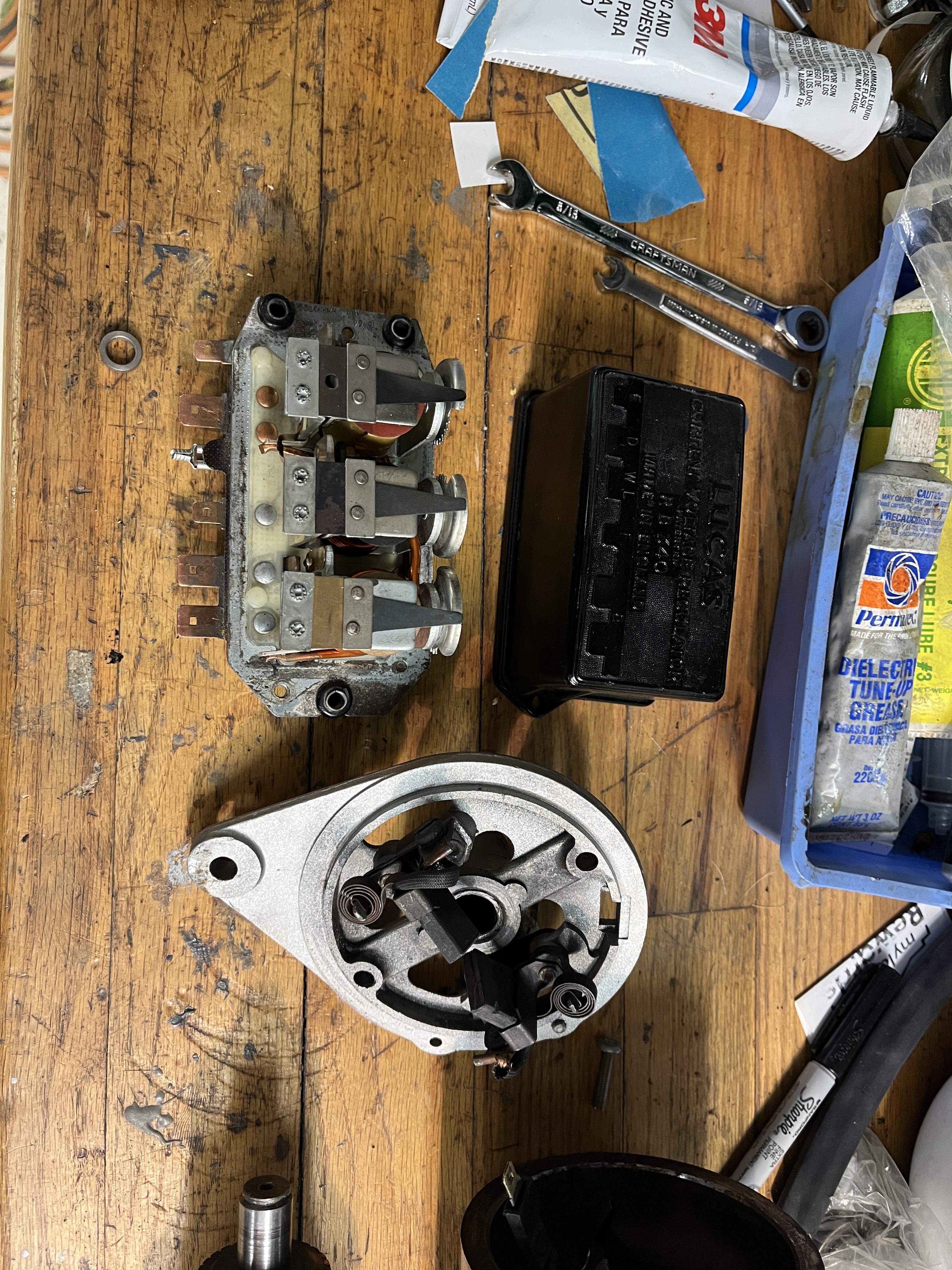
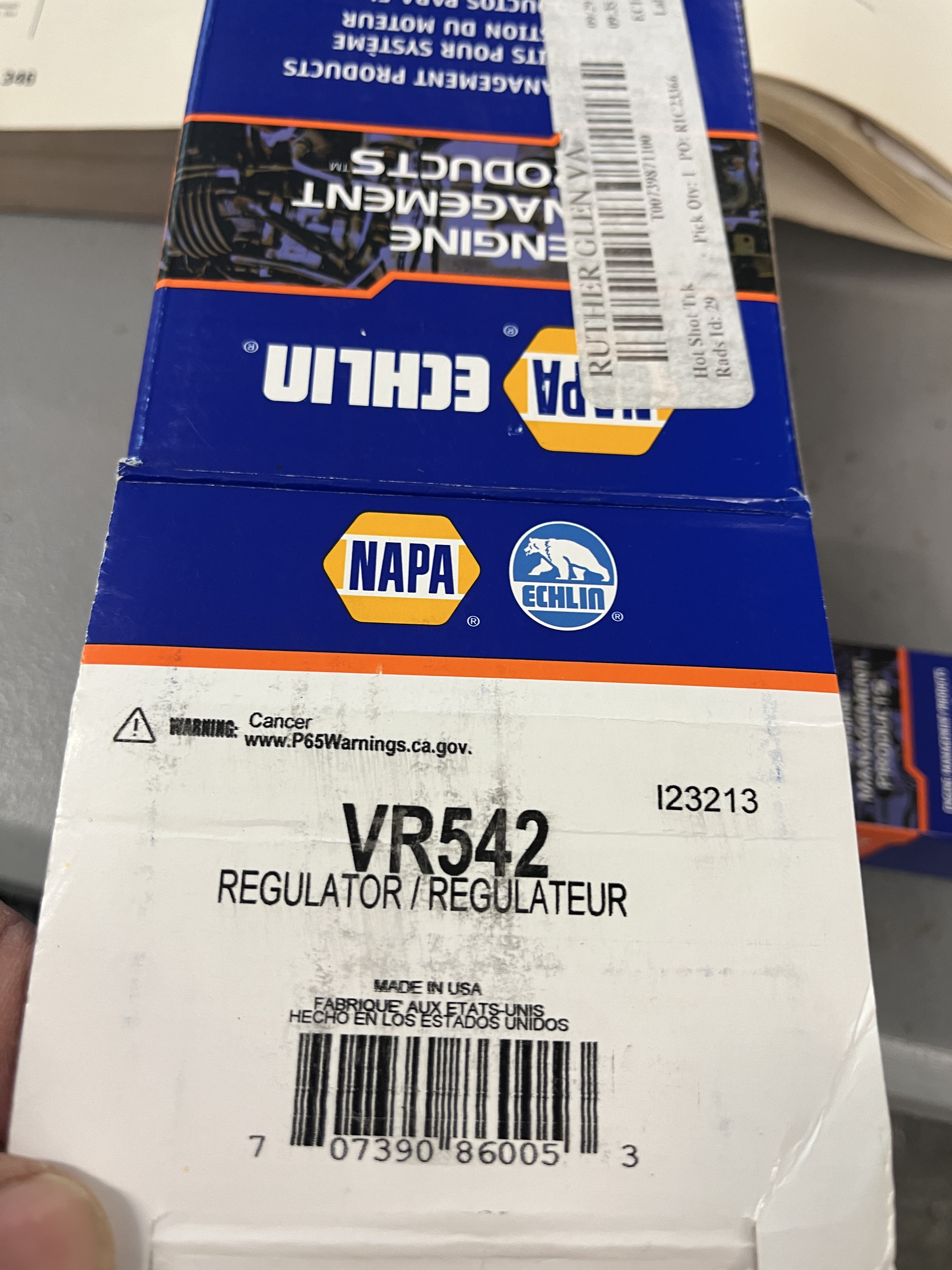
I had an original RB340 VR in my box of parts. After much diagnostic work, I determined that I could not salvage it. The contact points were in bad shape. I could never get it to regulate the voltage correctly, much less the current. I wound up buying a new aftermarket VR from NAPA/Echlin. It is stamped Made in America. It has a similar shape factor as the original Lucas device. The terminal connections are exactly the same. I hooked it up and after running the tests from the Lucas Generator and Control Box Tests document, it seemed to be operating correctly.
The 3 screw pattern to connect the Echlin VR to the mounting bracket are the same. The mounting holes for the waterproof cover are not the same. To make it look original, I was able to mount the original RB-340 cover but this required drilling and tapping some new holes. Once installed, it would take a sharp eye to spot it versus the original.
You might ask why I am messing with a generator and its associated VR. The main reason is for purposes of originality. SNG and others sell various versions of a more modern alternator that is concealed in a housing that is a drop in replacement for the generator. SNG even sells a “mock” RB340 housing. That said, the wiring for an alternator is simpler and is an obvious “tell” for this type of installation. Except for JCNA Champion class concours competition, the alternator product is probably the way to go, from a reliability and electrical performance standpoint.
Below are some pictures showing various aspects of this work.


Discussion
Comments are closed.