As many of you will know, the Series 1 Etype was fitted with three SU (Skinners Union) carbs. Much has been written about the SU carb design, which is ubiquitous on English cars of that era, similar to Weber carbs being used on Italian cars. Google “constant depression carb” for more technical details. The displacement of the Etype at 3.8 litres just barely warranted 3 carbs versus 2 but this is probably a case where the marketing department overrode the bean counters.
The 3 SU carbs that came in my box of parts had been sitting on a shelf for many years. Early this year, I boxed them up and sent them to Joe Curto in NYC. I recently did an article on Joe, who is quite the legend in the world of SU carbs. He performed a mechanical and cosmetic restoration of the carbs. The results are pure eye candy!


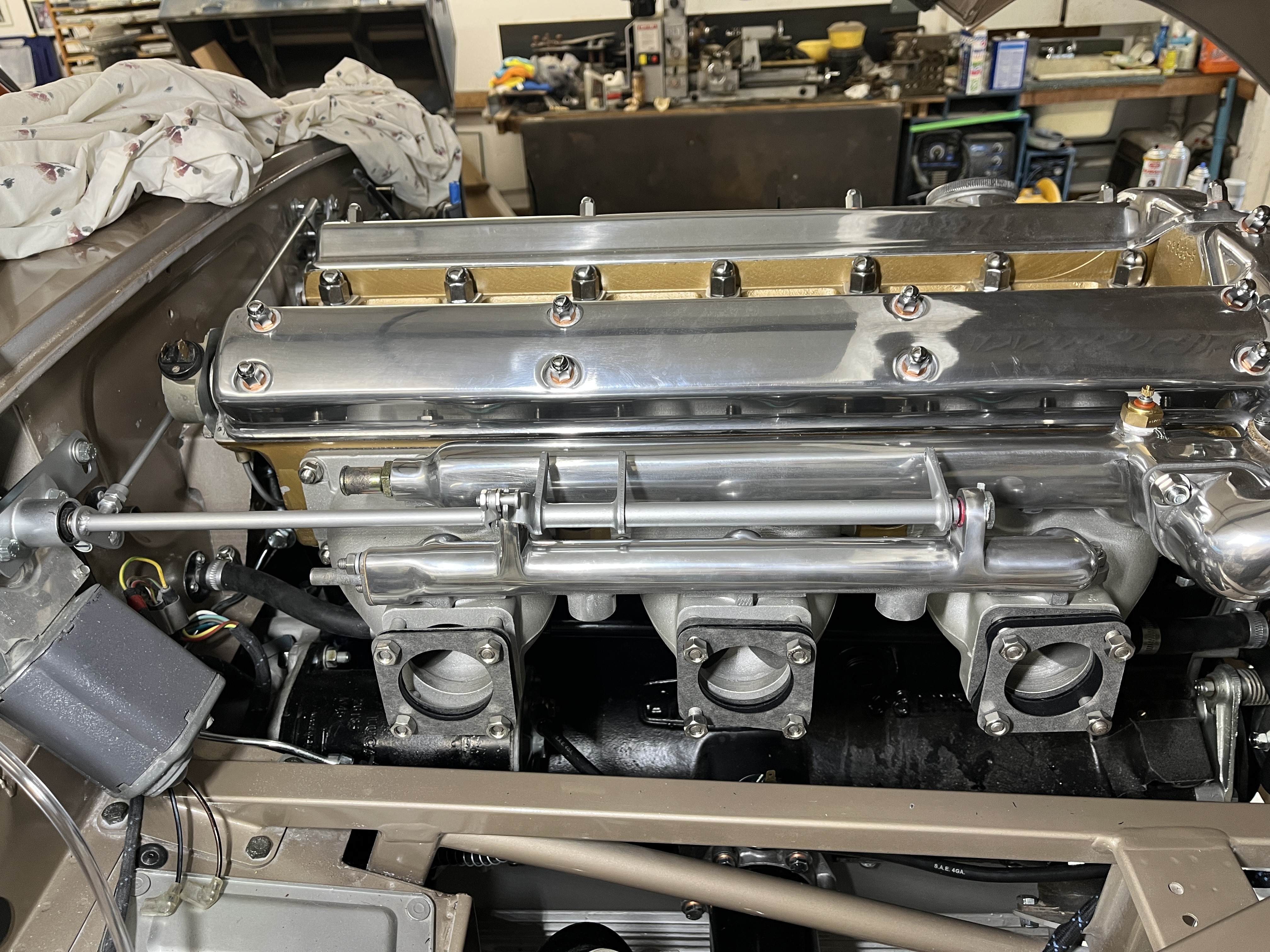
Prior to installing the carbs, I installed the 3 induction manifolds, the common manifold for coolant, and the common manifold for air balancing. The latter two items received a aluminum polish job. The induction manifolds are just plain sand cast aluminum. I also had to purchase some of the linkage items shown from SNG, as they had gone missing from my boxes.
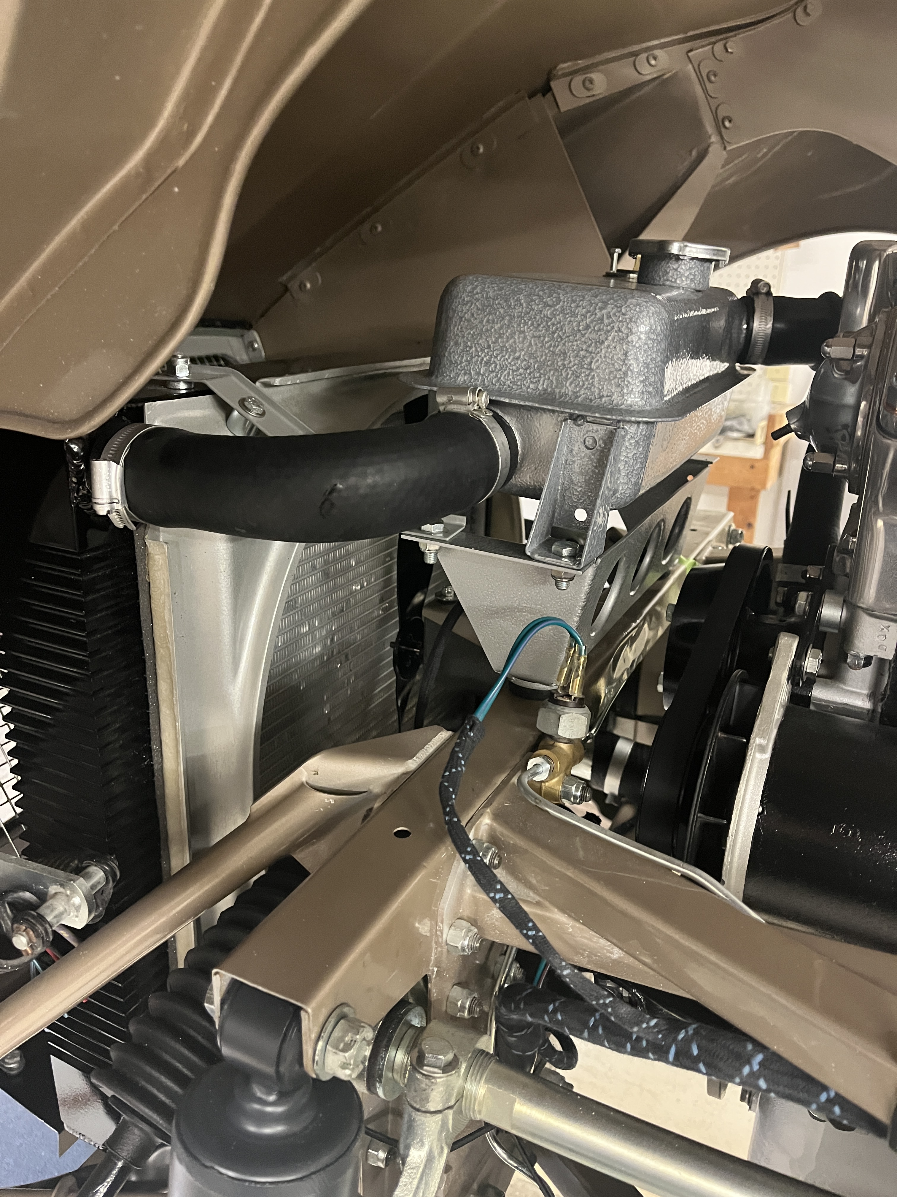
Another job I did before access got tight was to install the various coolant hoses and the thermostat housing. I used my stock of genuine Cheney clamps purchased on Ebay from Maurys Garage. As others will testify to, these do not inspire confidence but they are concours correct so we will see if they can hold pressure when I put the engine into service.


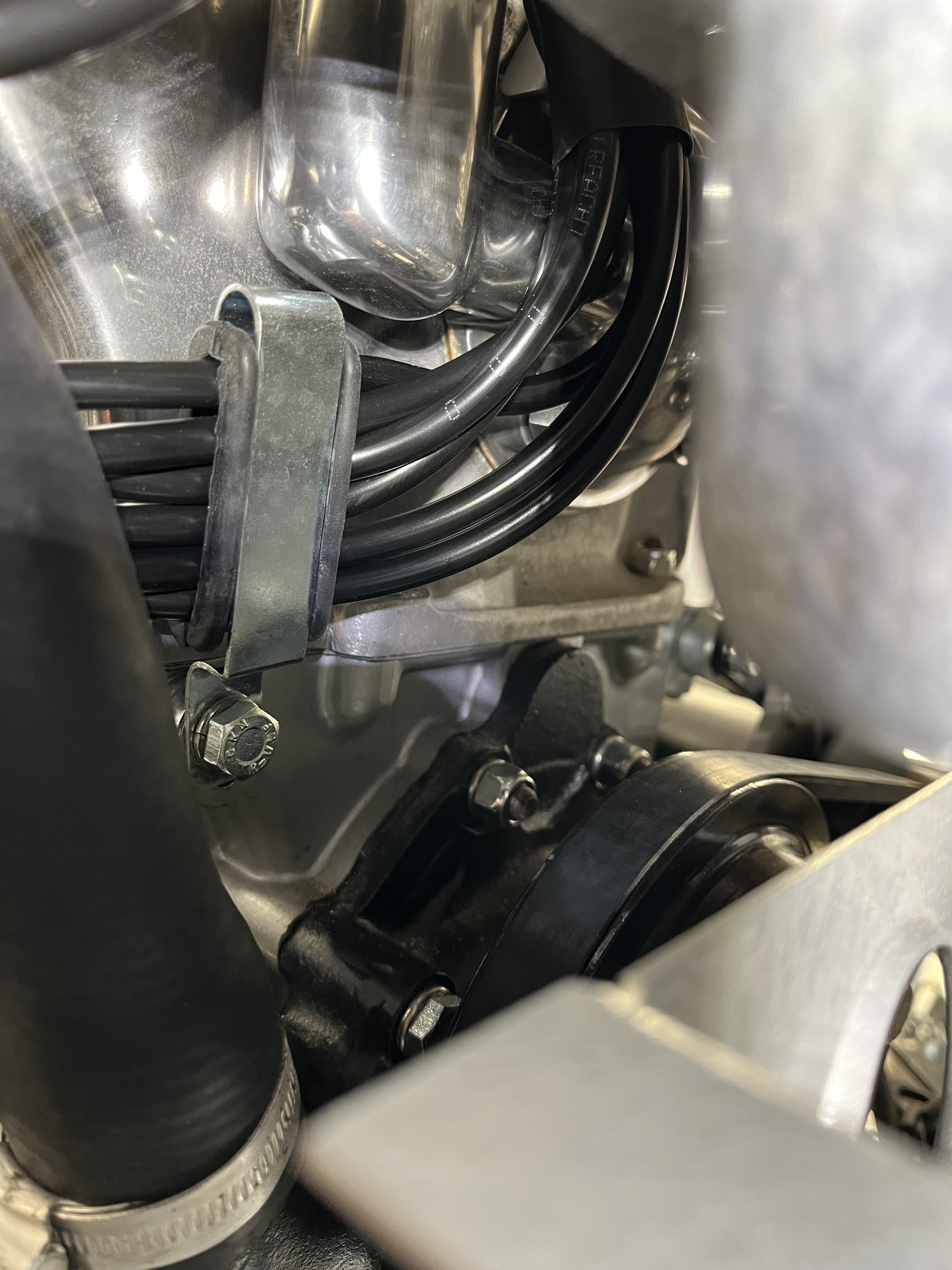
I also took this opportunity to install the distributor and the spark plug wires. The spark plug wires are old school solid copper core wires. I cut them to length, screwed a Champion cap on one end, and soldered a brass disc on the other end, which helps hold the wire in place with a screw cap on the distributor. The wires are inserted though a simple cardboard tube in the valley of the engine, which serves as an organizer.

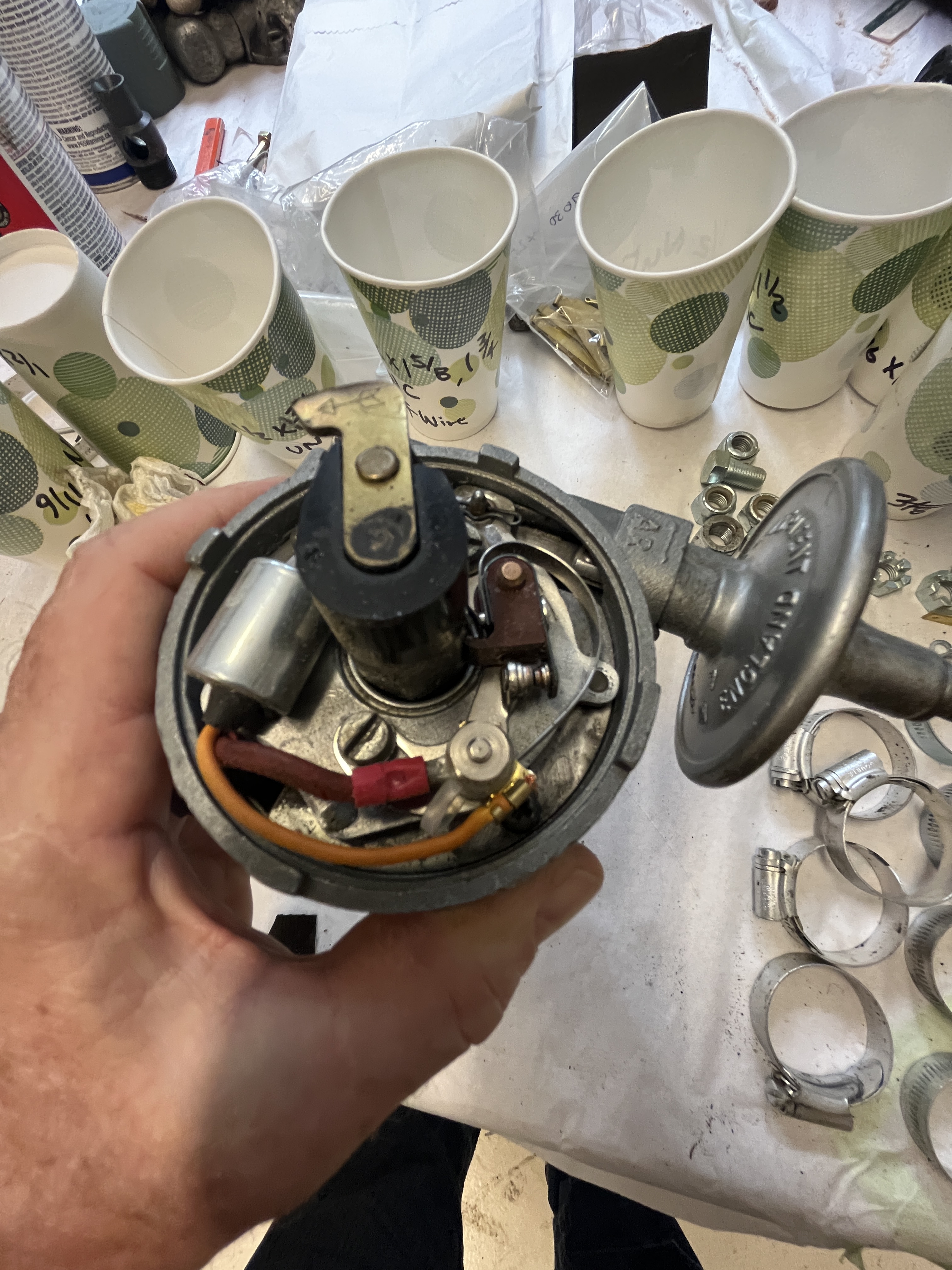
The distributor was rebuilt and tested by Dick Maury. I installed it into the block, where a cog engages to drive it at 1/2 of the crankshaft speed. The distributor includes a centrifugal advance unit was well as a vacuum advance. The centrifugal unit advances the spark with increasing rpm’s of the engine. The vacuum unit advances the spark at “light throttle”, which is basically a fuel economy measure.

Going back to the carburators, I hooked up the linkages. Joe Curto had done a nice job with the throttle shafts so they opened and closed very crisply. I hooked all 3 carbs up to the common throttle shaft and roughly set them to open equally. I will make final adjustments when the engine is running, using a Unisyn to balance air flow. I also hooked up the choke cable that is controlled by a lever on the right hand side of the dash. I confirmed visually that all 3 choke mechanisms were activating roughly equally.
After I got the carbs squared away, it was time to look at the air filter assembly. Some research on the UK Factory Fit forum indicated that some of the components I had on hand were not correct or complete. The most glaring issue was the triangular air intake assembly. In the summer of 1963, cars were noted with 3 “grooves” in the top of this piece but before that they were flat topped. An educated guess is that the flat top assembly was prone to cracking or outright collapse. Regardless, the piece I had on hand from my “box of parts” had the grooves, which would be incorrect for my January 2nd, 1963 build date. Additionally, the round canister that holds the paper filter assembly was missing its internal parts. Fortunately, SNG sells very nice reproductions of both of these parts. BTW, the correct finishes are black for the round canister and silver Hammerite for the triangular plenum. I was able to use my existing “trumpet assembly” which externally has 3 tubes and that internally has “velocity stack” entrances to the 3 tubes, which adds a modicum of performance at high rpms. Even better was the fact that a standard Rustoleum Silver Hammerite was an excellent match to the finish on the SNG part. Once I had these parts on hand, it was mainly a matter of reviewing the SPC for the correct fasteners and hooking everything up. BTW when the bonnet is closed, those 2 “snorkles” line up with the outlet of the fresh air intake on the right hand side of the bonnet, delivering relatively cool air to the carbs.


But nothing is ever easy on these cars. Installing the trumpet assembly gave me one terminal end of the crankcase “breather” pipe, which originates at a fitting on the front of the timing cover. The breather basically takes hot oily fumes from the crankcase and feeds them back into the intake tract for combustion. I had purchased a breather pipe from SNG. It is an unusual shape and I assume that the SNG version was based on a sampling of those found on various cars. That said, I lost several hours experimenting with small tweaks to the routing. I wound up having to reshape the tubes slightly but not too bad all in all. They pass through the same area as the distributor, the spark plug leads, and the coolant hoses. All I’m going to say is that space is a premium at the right hand front side of an XK engine!
I have obtained a period correct Lucas ignition coil from RWAutoClassics. Although it passes basic resistance checks, I have also purchased an aftermarket coil which I will used for initial startup and testing of the engine. As an aside, I learned from Jag-Lovers that the markings on the coil, SW and CB, stand for switch and contact breaker, which refers to the points in the distributor. Sometimes it’s the little things that separate a routine restoration from a great restoration!

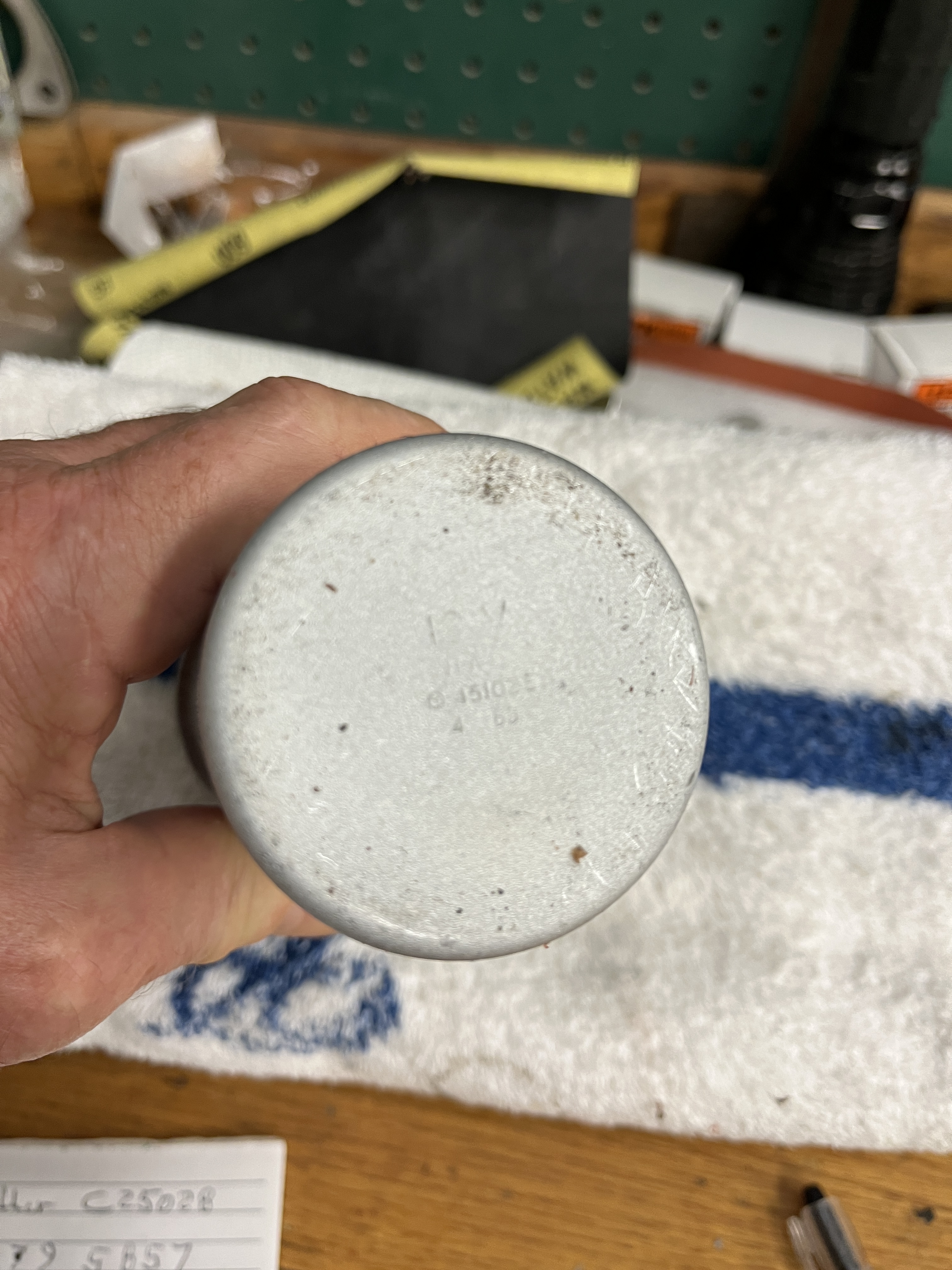
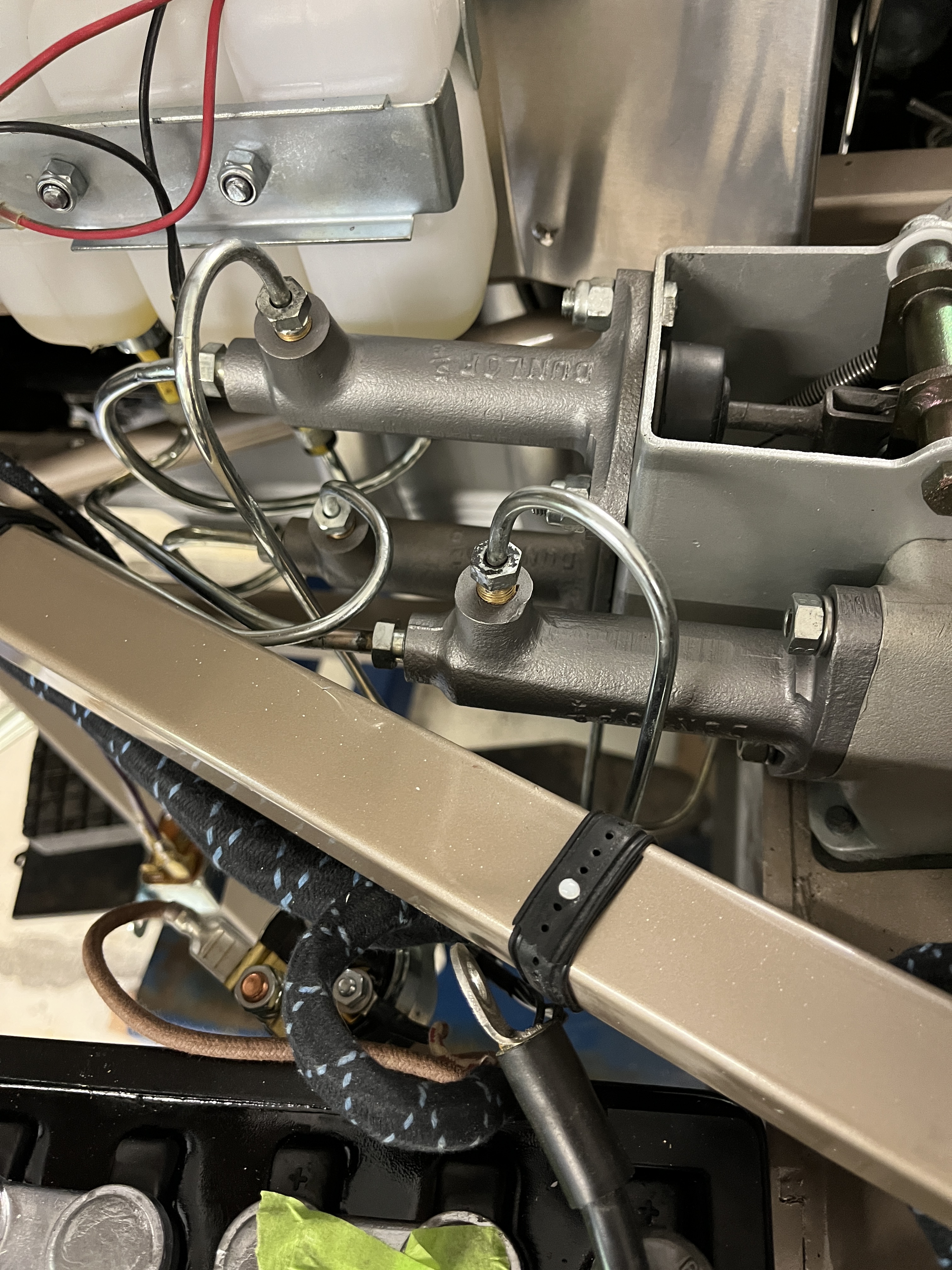
Last but not least, I had to deal with a situation on my brake and clutch master cylinders. I had sent them to White Post Restorations to be sleeved and new rubber parts installed. They painted the exteriors with a rather pedestrian grey paint. The JCNA Autenticity Guide states that a “Clutch & brake cylinders have a natural cast iron finish”. Well, the natural state of cast iron is rust but clearly that is not what we are looking for. After some research, I decided to bead blast the cylinders and seal the unprotected cast iron surface with a product called ACF-50. It is not a “lifetime” solution but the corrosion protection of the ACF-50 is said to measure in years, not months. Time will tell. BTW, a small detail evident in this photo. If you follow the SPC closely, it calls for self-locking nuts on the brake master cylinders but standard nuts with a clockwasher on the clutch master cylinder. Go figure!
Although the engine is very close to full functionality, I don’t plan on starting it until pretty much the last thing. It is good to break the engine in, especially the rings, by driving the engine at varying speeds under a light load. So I’ll want to have the car basically licensed and ready to go when I do initial startup on the engine. I can’t wait!

Discussion
Comments are closed.